Download
1 / 50
510 likes | 957 Views
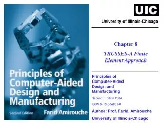
University of Illinois-Chicago. Chapter 8 TRUSSES-A Finite Element Approach. Principles of Computer-Aided Design and Manufacturing Second Edition 2004 ISBN 0-13-064631-8 Author: Prof. Farid. Amirouche University of Illinois-Chicago. CHAPTER 8. 8.1 Introduction to Truss Analysis.

E N D
University of Illinois-Chicago Chapter 8 TRUSSES-A Finite Element Approach Principles of Computer-Aided Design and Manufacturing Second Edition 2004 ISBN 0-13-064631-8 Author: Prof. Farid. Amirouche University of Illinois-Chicago
CHAPTER 8 8.1 Introduction to Truss Analysis 8.1 Introduction to truss analysis Trusses are used in many engineering applications including bridges, buildings, and towers and support structures. In a truss, we are faced with a structure where the displacements, translations, or compressions of any truss member vary linearly with the applied forces. That is, any increment in displacement is proportional to the force causing it to deform. All deformations are assumed small, so that the resulting displacements do not significantly affect the geometry of the structure and hence do not alter the forces in the members. In this case Hooke’s Law is preserved and the theory of elasticity is used to search for solutions of the truss. Most often, the truss design requires that its member be tested for tension, compression, stress, and strain relations. The applied loads are then tested against the possible yield stress to determine their evaluated limits and the overall stability of the truss. Principles of Computer-Aided Design and Manufacturing Second Edition 2004 – ISBN 0-13-064631-8 Author: Prof. Farid. Amirouche, University of Illinois-Chicago
CHAPTER 8 8.1 Introduction to Truss Analysis Figure 8.1 A planar truss subject to vertical loads (P1, P2 P3 represent arbitrary) loads Principles of Computer-Aided Design and Manufacturing Second Edition 2004 – ISBN 0-13-064631-8 Author: Prof. Farid. Amirouche, University of Illinois-Chicago
CHAPTER 8 8.2 Finite Element Formulation 8.2 Finite Element Formulation Trusses are typical structures in which the finite-element method can be best illustrated. We know that FEM relies on (a) discretizing the finite element of the system, (b) developing the mathematical relationships between the forces and displacements, stresses and strains, etc., for a given element, and (c) formulating the general problem through an assembly procedure of all the elements to solve the given problem Principles of Computer-Aided Design and Manufacturing Second Edition 2004 – ISBN 0-13-064631-8 Author: Prof. Farid. Amirouche, University of Illinois-Chicago
CHAPTER 8 8.2 Finite Element Formulation Consider an element of an arbitrary truss, as shown in Figure 8.1. It is subjected to either tension or compression, as is the case for all the truss elements. Let us label the element’s ends 1 and 2, and, consequently, call the corresponding forces F1 and F2 (Fig 8.2). F1 F2 Figure 8.2 A typical truss element (8.1) (8.2) or (8.3) Principles of Computer-Aided Design and Manufacturing Second Edition 2004 – ISBN 0-13-064631-8 Author: Prof. Farid. Amirouche, University of Illinois-Chicago
CHAPTER 8 8.2 Finite Element Formulation Relative displacement can be written as (8.4) From Equation (8.3) (8.5) and (8.6) (8.7) or (8.8) where The nodal force vector for the element The nodal displacement vector The element stiffness matrix Principles of Computer-Aided Design and Manufacturing Second Edition 2004 – ISBN 0-13-064631-8 Author: Prof. Farid. Amirouche, University of Illinois-Chicago
CHAPTER 8 8.2 Finite Element Formulation Let us consider an orientation of a truss element, as shown in Figure 8.3. we define the element force components as follows: (8.9) (8.10) Figure 8.3 A truss element making an angle with the x-axis Principles of Computer-Aided Design and Manufacturing Second Edition 2004 – ISBN 0-13-064631-8 Author: Prof. Farid. Amirouche, University of Illinois-Chicago
CHAPTER 8 8.2 Finite Element Formulation Given that the relative displacement u is along the unit vector ν, then (8.11) where (8.12) and (8.13) then by substitution of Equations (8.13) and (8.12) into Equation (8.11) and making use of Equations (8.3), (8.9), and (8.10), we obtain an expression for each nodal force in terms of the local displacement, the orientation and the element stiffness K. (8.14) (8.15) (8.16) (8.17) Principles of Computer-Aided Design and Manufacturing Second Edition 2004 – ISBN 0-13-064631-8 Author: Prof. Farid. Amirouche, University of Illinois-Chicago
CHAPTER 8 8.2 Finite Element Formulation Writing Equations (8.14) through (8.17) in matrix form yields (8.18) where s and c are abbreviations for sin and cos , respectively, and k is the stiffness constant. We can write Equation (8.18) in more compact form as (8.19) where and (8.21) Principles of Computer-Aided Design and Manufacturing Second Edition 2004 – ISBN 0-13-064631-8 Author: Prof. Farid. Amirouche, University of Illinois-Chicago
CHAPTER 8 8.2 Finite Element Formulation For =0, The local stiffness matrix is simply (8.22) Which checks with Equation (8.8). Note how the zero rows and columns are simply used to expand the local stiffness matrix given by Equation (8.8) to account for the zero forces and displacements along the y-axis. Principles of Computer-Aided Design and Manufacturing Second Edition 2004 – ISBN 0-13-064631-8 Author: Prof. Farid. Amirouche, University of Illinois-Chicago
CHAPTER 8 8.3 Properties of the Local Stiffness Matrix 8.3 Properties of the Local Stiffness Matrix First, we observe that the local stiffness matrix is symmetric and that its coefficients are functions of cos and sin. In addition, let the local stiffness be partitioned as follows: (8.23) where we can see that the partitioned matrices A, B, C, and D are such that It is evident from the partition and this relationship stated above that we can deduce the following criteria to build the local stiffness: we only need to know sub matrix 1, and then sub matrix B is obtained by pre multiplying A by -A; C and D are then obtained from A and B, respectively. (8.24) Principles of Computer-Aided Design and Manufacturing Second Edition 2004 – ISBN 0-13-064631-8 Author: Prof. Farid. Amirouche, University of Illinois-Chicago
CHAPTER 8 8.4 Global Stiffness Matrix 8.4 GLOBAL STIFFNESS MATRIX The method that is illustrated in what follows to obtain the global stiffness matrix is one that Huston and Passerelo have developed. It shows how the building of the global stiffness matrix can be done by a simple strategy in which connectivity tables are used to identify the truss elements and their joints. The method is as follows. Step 1. Consider an arbitrary truss, as shown in Figure 8.4. First, label the truss elements and joints in an arbitrary fashion, as shown in Figure 8.4. There are five joints (1, 2, …, 5) and seven elements ([1], [2],…, [7]). Step 2. We proceed to develop three tables that basically store geometrical information about the truss. Table 8.1 has the truss-joint/matrix-column matching, where pairs starting from 1 develop the column numbers, 2. Principles of Computer-Aided Design and Manufacturing Second Edition 2004 – ISBN 0-13-064631-8 Author: Prof. Farid. Amirouche, University of Illinois-Chicago
CHAPTER 8 8.4 Global Stiffness Matrix Table 8.2 identifies the connection joints to all the elements of the truss. Principles of Computer-Aided Design and Manufacturing Second Edition 2004 – ISBN 0-13-064631-8 Author: Prof. Farid. Amirouche, University of Illinois-Chicago
CHAPTER 8 8.4 Global Stiffness Matrix TABLE 8.1 TRUSS –JOINT/MATRIX COLUMN MATRIX TABLE 8.2 ELEMENTS Vs JOINT NUMBERS Principles of Computer-Aided Design and Manufacturing Second Edition 2004 – ISBN 0-13-064631-8 Author: Prof. Farid. Amirouche, University of Illinois-Chicago
CHAPTER 8 8.4 Global Stiffness Matrix TABLE 8.3 TRUSS ELEMENTS Vs kije Principles of Computer-Aided Design and Manufacturing Second Edition 2004 – ISBN 0-13-064631-8 Author: Prof. Farid. Amirouche, University of Illinois-Chicago
CHAPTER 8 8.4 Global Stiffness Matrix Global forces and displacements: (8.25) Where (8.26) And (8.27) Principles of Computer-Aided Design and Manufacturing Second Edition 2004 – ISBN 0-13-064631-8 Author: Prof. Farid. Amirouche, University of Illinois-Chicago
CHAPTER 8 8.4 Global Stiffness Matrix Thus, the [K] in Equation (8.27) is the assembled global stiffness matrix obtained from the assembly of individual element stiffness matrices, that is, (8.28) where is the local element stiffness matrix given by (8.23) (8.29) For =90 Principles of Computer-Aided Design and Manufacturing Second Edition 2004 – ISBN 0-13-064631-8 Author: Prof. Farid. Amirouche, University of Illinois-Chicago
CHAPTER 8 8.4 Global Stiffness Matrix For element 1 For element 2 For element 5 (8.33) The global stiffness is found to be : Principles of Computer-Aided Design and Manufacturing Second Edition 2004 – ISBN 0-13-064631-8 Author: Prof. Farid. Amirouche, University of Illinois-Chicago
CHAPTER 8 8.4 Global Stiffness Matrix Principles of Computer-Aided Design and Manufacturing Second Edition 2004 – ISBN 0-13-064631-8 Author: Prof. Farid. Amirouche, University of Illinois-Chicago
CHAPTER 8 8.5 Solution of the Truss Problem 8.5 SOLUTION OF THE TRUSS PROBLEM For the truss shown in Figure (8.4) we have: Thus, , (8.36) (8.35) , Roller joint at 2 in y-dir , Force P in the x-dir at joint 5 . Principles of Computer-Aided Design and Manufacturing Second Edition 2004 – ISBN 0-13-064631-8 Author: Prof. Farid. Amirouche, University of Illinois-Chicago
CHAPTER 8 8.5 Solution of the Truss Problem The displacement boundary conditions are: (8.38) Principles of Computer-Aided Design and Manufacturing Second Edition 2004 – ISBN 0-13-064631-8 Author: Prof. Farid. Amirouche, University of Illinois-Chicago
CHAPTER 8 8.5 Solution of the Truss Problem Substituting [F] and [U] from Equations (8.36) and (8.38) into Equation (8.25), we obtain the general equations governing the truss force/displacement equilibrium conditions. (8.39) Principles of Computer-Aided Design and Manufacturing Second Edition 2004 – ISBN 0-13-064631-8 Author: Prof. Farid. Amirouche, University of Illinois-Chicago
CHAPTER 8 8.5 Solution of the Truss Problem Note how in Equation (8.39) the unknowns are in the global force array as well as in the joint displacement vector. A typical strategy to solve such a problem in which the unknowns are on both sides of the equation is to solve for the U’s first by partitioning the matrices such that the force vector is completely in terms of the known forces. Eliminating the reaction forces does the partitioning. The resulting equation is : (8.40) (8.41) Principles of Computer-Aided Design and Manufacturing Second Edition 2004 – ISBN 0-13-064631-8 Author: Prof. Farid. Amirouche, University of Illinois-Chicago
CHAPTER 8 8.5 Solution of the Truss Problem Once the equations are solved for the displacements, reactions R1x, R1y, and R2y can be evaluated by Pre-multiplying the corresponding terms of [K] and [U] in Equation (8.39). The solutions are found to be : (8.42) Principles of Computer-Aided Design and Manufacturing Second Edition 2004 – ISBN 0-13-064631-8 Author: Prof. Farid. Amirouche, University of Illinois-Chicago
CHAPTER 8 8.5 Solution of the Truss Problem The answers obtained from the FEM analysis as described before can be checked by simply taking the free-body diagram for the truss as shown in Figure 8.5. Figure 8.5 A simple free-body diagram of 2D truss subject to loading Principles of Computer-Aided Design and Manufacturing Second Edition 2004 – ISBN 0-13-064631-8 Author: Prof. Farid. Amirouche, University of Illinois-Chicago
CHAPTER 8 8.5 Solution of the Truss Problem Writing the equilibrium equations (8.43) We get (8.44) Which checks with the FEM solution. Principles of Computer-Aided Design and Manufacturing Second Edition 2004 – ISBN 0-13-064631-8 Author: Prof. Farid. Amirouche, University of Illinois-Chicago
CHAPTER 8 8.6 Evaluation of the Local Forces • 8.6 EVALUATION OF THE LOCAL FORCES The internal forces are those that are either compressing or causing the truss elements in tension. To find the components of the forces acting at each end, we use the previously computed global displacements and local stiffness matrix. From Equation (8.21), we have (8.45) Principles of Computer-Aided Design and Manufacturing Second Edition 2004 – ISBN 0-13-064631-8 Author: Prof. Farid. Amirouche, University of Illinois-Chicago
CHAPTER 8 8.6 Evaluation of the Local Forces Let the local displacement be written as ueij, where e is the element number of the truss, i denotes either end 1 or end 2 of the element, and j assigns the direction x or y to the end displacements. Assuming that all elements of the truss undergo the same displacements at each joint, we then write the following : For joint 1: For joint 2: (8.46) (8.47) For joint 3: (8.48) Principles of Computer-Aided Design and Manufacturing Second Edition 2004 – ISBN 0-13-064631-8 Author: Prof. Farid. Amirouche, University of Illinois-Chicago
CHAPTER 8 8.6 Evaluation of the Local Forces For joint 5 For joint 4: (8.49) (8.50) The nodal displacements for any particular element can be found from the relationships between the global displacements and the local displacement by using Equation (8.46) to (8.50). Subsequent substitution of these values for a particular element in Equation (8.45) and multiplying by the corresponding stiffness matrix terms yield the nodal forces. The signs of these forces indicate whether the member is in tension or compression. Principles of Computer-Aided Design and Manufacturing Second Edition 2004 – ISBN 0-13-064631-8 Author: Prof. Farid. Amirouche, University of Illinois-Chicago
CHAPTER 8 8.6 Evaluation of the Local Forces Example 8.1 Analysis of a Three-Element Truss Use the finite-element method to solve for the truss in the following figure a) Find the global stiffness matrix. b) Solve for the reaction forces. c) Solve for the member forces and determine whether a truss element is in tension or compression. Solution : The first step in our analysis is to label the truss for the joint numbers and link numbers as shown in the Figure (8.6). The second step is to compute the local stiffness matrices for each member using Equation (8.21). Principles of Computer-Aided Design and Manufacturing Second Edition 2004 – ISBN 0-13-064631-8 Author: Prof. Farid. Amirouche, University of Illinois-Chicago
CHAPTER 8 8.6 Evaluation of the Local Forces P = 100 lb F1x F1y F2y Figure 8.6 A three-element truss subject to loading Principles of Computer-Aided Design and Manufacturing Second Edition 2004 – ISBN 0-13-064631-8 Author: Prof. Farid. Amirouche, University of Illinois-Chicago
CHAPTER 8 8.6 Evaluation of the Local Forces The element stiffness matrices are : Principles of Computer-Aided Design and Manufacturing Second Edition 2004 – ISBN 0-13-064631-8 Author: Prof. Farid. Amirouche, University of Illinois-Chicago
CHAPTER 8 8.6 Evaluation of the Local Forces Where A1,A2,A3 and L1,L2,L3 are the areas of cross section and lengths of the members of the truss, respectively, and E is the young’s modulus of elasticity. And L1= 1 , such that Now let us construct Tables 8.4 to 8.6 (see earlier Tables 8.1 to 8.3), which help in arriving at the global stiffness matrix K. Principles of Computer-Aided Design and Manufacturing Second Edition 2004 – ISBN 0-13-064631-8 Author: Prof. Farid. Amirouche, University of Illinois-Chicago
CHAPTER 8 8.6 Evaluation of the Local Forces Table 8.4 Table 8.5 Table 8.6 Principles of Computer-Aided Design and Manufacturing Second Edition 2004 – ISBN 0-13-064631-8 Author: Prof. Farid. Amirouche, University of Illinois-Chicago
CHAPTER 8 8.6 Evaluation of the Local Forces Using the local stiffness matrices and transferring the entries with the help of Table 8.6 we can arrive at the global stiffness matrix: Zeros in the force vector indicate that the forces in the x and y directions at joints 2 and 3 are zeroes because of the roller and free joint, respectively. Principles of Computer-Aided Design and Manufacturing Second Edition 2004 – ISBN 0-13-064631-8 Author: Prof. Farid. Amirouche, University of Illinois-Chicago
CHAPTER 8 8.6 Evaluation of the Local Forces Applying the displacement boundary conditions, U1x=0, U1y=0, U2y=0, and eliminating the corresponding rows and columns, we get Solving for the unknowns, we obtain Principles of Computer-Aided Design and Manufacturing Second Edition 2004 – ISBN 0-13-064631-8 Author: Prof. Farid. Amirouche, University of Illinois-Chicago
CHAPTER 8 8.6 Evaluation of the Local Forces The reaction forces can be computed using Equation (8.43) as Principles of Computer-Aided Design and Manufacturing Second Edition 2004 – ISBN 0-13-064631-8 Author: Prof. Farid. Amirouche, University of Illinois-Chicago
CHAPTER 8 8.6 Evaluation of the Local Forces These results can be verified using the free-body diagram of the truss. Therefore, members 1 and 3 are in tension, whereas member 2 is in compression. Principles of Computer-Aided Design and Manufacturing Second Edition 2004 – ISBN 0-13-064631-8 Author: Prof. Farid. Amirouche, University of Illinois-Chicago
CHAPTER 8 8.6 Evaluation of the Local Forces The member forces are obtained from the local element force-displacement relationship: The global and local displacement at each joints are related as follows : Principles of Computer-Aided Design and Manufacturing Second Edition 2004 – ISBN 0-13-064631-8 Author: Prof. Farid. Amirouche, University of Illinois-Chicago
CHAPTER 8 8.6 Evaluation of the Local Forces Using the local stiffness already computed and given by Equation (8.51) to (8.53), we obtain the element: The forces acting on element 1 clearly show that it is in tension as predicted. Similarly, we can obtain the magnitude of the forces and directions for elements 2 and 3. Principles of Computer-Aided Design and Manufacturing Second Edition 2004 – ISBN 0-13-064631-8 Author: Prof. Farid. Amirouche, University of Illinois-Chicago
CHAPTER 8 8.7 Stress Analysis 8.7 Stress Analysis In the analysis of truss the main objective is to decide whether the truss elements are designed to sustain the load they support. For that we need to evaluate the stress or average stress in each element. The latter is an indication as to whether the tension or compression can be sustained. Let the element stress be given by (8.51) (8.52) Now we can compute the stress for each element of the truss in previous example 8.4. For each element we can write Principles of Computer-Aided Design and Manufacturing Second Edition 2004 – ISBN 0-13-064631-8 Author: Prof. Farid. Amirouche, University of Illinois-Chicago
CHAPTER 8 8.7 Stress Analysis And the results are Principles of Computer-Aided Design and Manufacturing Second Edition 2004 – ISBN 0-13-064631-8 Author: Prof. Farid. Amirouche, University of Illinois-Chicago
CHAPTER 8 8.8 Force and Displacement Incidence Matrices 8.8 Force, and Displacement Incidence Matrices The global forces and local forces as well their corresponding global and local displacements can be shown to have special relationships that can be found by means of incidence matrices. These matrices are derived by examining the global and local displacement relation at the nodes and joints of the truss. Similarly the global or local displacement relation for joint 2 and 3 can be expressed as Principles of Computer-Aided Design and Manufacturing Second Edition 2004 – ISBN 0-13-064631-8 Author: Prof. Farid. Amirouche, University of Illinois-Chicago
CHAPTER 8 8.8 Force and Displacement Incidence Matrices Writing the above relations in a matrix form yields Where Principles of Computer-Aided Design and Manufacturing Second Edition 2004 – ISBN 0-13-064631-8 Author: Prof. Farid. Amirouche, University of Illinois-Chicago
CHAPTER 8 8.8 Force and Displacement Incidence Matrices Element 2 Element 1 Element 3 (8.53) denotes the incidence matrix for element (e). We can develop a relationship between the global forces and the local forces by noting that (8.54) Principles of Computer-Aided Design and Manufacturing Second Edition 2004 – ISBN 0-13-064631-8 Author: Prof. Farid. Amirouche, University of Illinois-Chicago
CHAPTER 8 8.8 Force and Displacement Incidence Matrices And from the global Force/Displacement relation (8.55) We rewrite [F] as function of the local displacement by substituting equation (8.54) into the above equation (8.56) The above global force represents the contribution of element e to the global force vector [F]. Hence the total force vector is obtained by summing the contribution of all the elements such that (8.57) From the local force/displacement (8.58) we rewrite the global force equation as (8.59) Principles of Computer-Aided Design and Manufacturing Second Edition 2004 – ISBN 0-13-064631-8 Author: Prof. Farid. Amirouche, University of Illinois-Chicago
CHAPTER 8 8.8 Force and Displacement Incidence Matrices Substituting the local displacements as function of the incidence matrix and local forces we obtain (8.60) where [k]-1=[k]T . Let us define (8.61) Then we write the relationship between the local forces and global forces as (8.62) (8.63) For each element we can derive the corresponding local forces from the existing information on [F] used in the global formulation of the FE problems. This is done quite interactively if large codes are needed. Principles of Computer-Aided Design and Manufacturing Second Edition 2004 – ISBN 0-13-064631-8 Author: Prof. Farid. Amirouche, University of Illinois-Chicago
CHAPTER 8 8.9 3-D Analysis of trusses 8.9 3-D Analysis of trusses The analysis of 3D truss is similar to the 2D case except the element stiffness must be developed for an arbitrary element in space. Consider such an element as shown in Figure 8.7 z j y i x Figure 8.7: The angle formed by a member with the x,y,z-axis. Principles of Computer-Aided Design and Manufacturing Second Edition 2004 – ISBN 0-13-064631-8 Author: Prof. Farid. Amirouche, University of Illinois-Chicago
CHAPTER 8 8.9 3-D Analysis of trusses The direction cosine with respect to each axis are given by (8.64) (8.65) (8.66) where L is the length of the member and is given by (8.67) Principles of Computer-Aided Design and Manufacturing Second Edition 2004 – ISBN 0-13-064631-8 Author: Prof. Farid. Amirouche, University of Illinois-Chicago
CHAPTER 8 8.9 3-D Analysis of trusses For a local element the force/displacement relation is given by (8.68) where Note how the nodes are represented by the subscripts 1 & 2 and the superscript denotes the element number . (8.69) Principles of Computer-Aided Design and Manufacturing Second Edition 2004 – ISBN 0-13-064631-8 Author: Prof. Farid. Amirouche, University of Illinois-Chicago