Design Technology and Computer Aided Design
820 likes | 1.05k Views
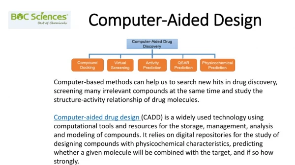
Design Technology and Computer Aided Design. Outline. Automation: synthesis Verification: hardware/software co-simulation Reuse: intellectual property cores Design process models. 2. Design task Define system functionality Convert functionality to physical implementation while

Design Technology and Computer Aided Design
E N D
Presentation Transcript
Outline Automation: synthesis Verification: hardware/software co-simulation Reuse: intellectual property cores Design process models 2
Design task Define system functionality Convert functionality to physical implementation while Satisfying constrained metrics Optimizing other design metrics Designing embedded systems is hard Complex functionality Millions of possible environment scenarios Competing, tightly constrained metrics Productivity gap As low as 10 lines of code or 100 transistors produced per day Introduction Who is winning? 3
Improving productivity Design technologies developed to improve productivity We focus on technologies advancing hardware/software unified view Automation Program replaces manual design Synthesis Reuse Predesigned components Cores General-purpose and single-purpose processors on single IC Verification Ensuring correctness/completeness of each design step Hardware/software co-simulation Specification Automation Verification Reuse Implementation Who is winning? 4
Automation: synthesis Early design automation was mostly for hardware Software complexity increased with advent of general-purpose processor Different techniques for software design and hardware design Caused division of the two fields Design tools evolve for higher levels of abstraction Different rate in each field Hardware/software design fields rejoining Both can start from behavioral description in sequential program model 30 years longer for hardware design to reach this step in the ladder Many more design dimensions Optimization critical The codesign ladder Sequential program code (e.g., C, VHDL) Behavioral synthesis (1990s) Compilers (1960s,1970s) Register transfers RT synthesis (1980s, 1990s) Assembly instructions Logic equations / FSM's Assemblers, linkers (1950s, 1960s) Logic synthesis (1970s, 1980s) Machine instructions Logic gates Implementation Microprocessor plus program bits VLSI, ASIC, or PLD implementation 5
Hardware/software parallel evolution Software design evolution Machine instructions Assemblers convert assembly programs into machine instructions Compilers translate sequential programs into assembly Hardware design evolution Interconnected logic gates Logic synthesis converts logic equations or FSMs into gates Register-transfer (RT) synthesis converts FSMDs into FSMs, logic equations, predesigned RT components (registers, adders, etc.) Behavioral synthesis converts sequential programs into FSMDs The codesign ladder Sequential program code (e.g., C, VHDL) Behavioral synthesis (1990s) Compilers (1960s,1970s) Register transfers RT synthesis (1980s, 1990s) Assembly instructions Logic equations / FSM's Assemblers, linkers (1950s, 1960s) Logic synthesis (1970s, 1980s) Machine instructions Logic gates Implementation Microprocessor plus program bits VLSI, ASIC, or PLD implementation 6
S S S S L L L S S S S L L L S S S S L L L S S S S Placement CLB netlist Assign logic to cells
Routing S S S S L L L S S S S L L L S S S S L L L S S S S Realize the interconnection by turning on switches of routing resources.
Placement & Routing Methods • Placement - simulated annealing is the commonly used method. • Routing - routability-driven and timing-driven. • Time-consuming design tasks. • Architectural dependent.
HDL-based Design Flow for Multi-FPGA Designs HDL description HDL synthesis Netlists Partitioning Partitioned netlists
Basic Partitioning Techniques • The min-cut partitioning: • The Kernighan-Lin algorithm. • The Fiduccia and Mattheyses algorithm. • The Krishnamurthy algorithm. • The ratio-cut algorithm. • A variety of clustering algorithms.
Multi-FPGA Partitioning • Constraints: • Fixed number of I/O pins in a device. • Fixed number of CLBs in a device. • Utilization of all devices. • Objectives: • 1. Cost minimization. • 2. Delay minimization.
Circuit-Level Partitioning Methods • Multiway partitioning methods based on the min-cut algorithm. • Interconnect minimization by cell replication. • Clustering-based partitioning methods - cone. • Combining top-down partitioning and bottom-up clustering methods.
Considerations for Multi-FPGA Partitioning • Limited IO-pin and logic resources. • Logic utilization is predominated by IO-pin limitation. • How to alleviate the IO-limitation problem is the key to improve the logic utilization of FPGA chips.
Combining HDL Synthesis and Partitioning HDL description HDL synthesis Bridging HDL synthesis and partitioning? Netlists Partitioning Partitioned netlists
Datapath-dominated Control-dominated Varying coding styles HDL Spec. Application-Oriented Synthesis Module-based Fine-grained Bit-sliced Function-based Design Considerations There are two main coding styles: datapath dominated and control dominated
Top Top Mod1 Mod2 Mod1_1 Mod2_1 M1 M2 Mod1_2 Mod2_2 M11 M12 M21 M22 Top Top M11 M12 M21 M22 M1 M2 Coding Styles hierarchical flattened
Top Top CU DP CU1 DP1 CU DP CU2 DP2 CU1 CU2 DP1 DP2 The FSMD Coding Style This design style used for FSMD is the same as we were doing so far in the class. It is good for small and medium processors
HDL descriptions Module-based HDL synthesis Fine-grained HDL synthesis Bit-sliced-based HDL synthesis Circuit-level partitioning Covering-based partitioning Bit-sliced-based partitioning P&R FPGAs Integrated HDL-Synthesis and Partitioning Methodology There are three basic synthesis and partitioning methodologies Placement and routing
Top M1 M2 Mn Module-based HDL Synthesis RAM, ROM, ALU, SHIFTER, COUNTER We plan modules top to bottom We build modules bottom to top Use, reuse and generate new types of hierarchical modules
Top M1 M2 Mn P1 Pm F1 F2 Clusters Fine-Grained HDL Synthesis The concept of process is used in VHDL and other languages It can be combinational or sequential processes NAND, NOR, Transistor, Buffer
Process{P1} input[0:3] i1,i2; input i3; output[0:3] o1; output o2; o1 = i1 + i2; o2 = i1[0] & i3; P1 o1 o2 i2 i1 i3 o1[0] o1[3] f2 4 4 f1.0 f1.3 + & 4 o1 o2 A Process Example Example of a process with natural partitioning
Design Design M1 M2 Module{M1} Process{P1} P1 P2 Process{P2} f1 f2 Module{M2} Functional-based Clustering Example of a module with partitioning to processes
[0] [5] [7] Mux Mux[0:7] Mux[0:5] Mux Adder Adder[0:7] Bit-Sliced-Based Synthesis One way of designing an adder with muxes is bit-slice partitioning Space wasted
DP Mux DP[0] [0] Mux[0] DP [7] Mux[0] Mux [0] Adder[0] [5] Mux[7] DP[7] Adder [0] [7] Adder[7] Functional Clustering These trees show different ways of partitioning or clustering Partitioning = top down, clustering = bottom up
An HDL-based Design Flow HDL design specification Verification versus validation versus simulation RTL synthesis Verification (Simulation) Logic synthesis Physical synthesis FPGAs
Design Specification • HDLs - VHDL and Verilog. • Why needs an HDL-based design methodology? • Target Applications. • Coding Styles. • Design representation. • Design entry. Topics to discuss
Why we need an HDL-based Design Methodology Design complexity Then Now Schematic capture HDL design specification Component mapping & may be some logic optimization Synthesis Place & route Place & route Layouts Layouts In SOFTWARE : assembly language => high-level language
Target Applications and Layout Architectures • Datapath dominateddesigns : DSPs and processors. • Control dominated designs: controllers and communication chips. • Mixed type of designs. • Bit-sliced stacks. • Standard cells. • Macro-cell-based. • FPGAs. Layout architectures So many variants. So little time. You must be laborious in industry applications
HDL Coding Styles versus Design Quality You can concentrate on ideas and use yours and other people experience Ideas? HDL spec1 HDL spec2 HDL spec3 You can create many variants also for many technologies Synthesis system Design2 Design3 Design1
Coding Styles and Design Representation • Hierarchical style • Structural style • Random style • FSMD • Behavioral level • Logic level • Gate level module MUX2(o,i1,i2,sel); output[1:4] o; input[1:4] i1,i2; input sel; assign o[1] = ((sel&i1[1])|(~sel&i2[1])); assign o[2] = ((sel&i1[2])|(~sel&i2[2])); assign o[3] = ((sel&i1[3])|(~sel&i2[3])); assign o[4] = ((sel&i1[4])|(~sel&i2[4])); endmodule module MUX2(o,i1,i2,sel); output[1:4] o; input[1:4] i1,i2; input sel; reg[1:4] o; always case(sel) 1’b0: o = i1; 1’b1: o = i2; endcase endmodule
RTL Synthesis • HDL compilation. • Design representation. • Component selection. • Component generation. • Resource sharing.
Register-transfer synthesis • Converts FSMD to custom single-purpose processor • Datapath • Register units to store variables • Complex data types • Functional units • Arithmetic operations • Connection units • Buses, MUXs • FSM controller • Controls datapath • Key sub problems: • Allocation • Instantiate storage, functional, connection units • Binding • Mapping FSMD operations to specific units
Behavioral synthesis • High-level synthesis • Converts single sequential program to single-purpose processor • Does not require the program to schedule states • Key sub problems • Allocation • Binding • Scheduling • Assign sequential program’s operations to states • Conversion templates • Optimizations important • Compiler • Constant propagation, dead-code elimination, loop unrolling • Advanced techniques for allocation, binding, scheduling
Ideally a totally automated tool with AI techniques should go through all good subspaces of the design space
Functional units Concurrent statements registers 3 solutions to Control Data Flow Graph
System synthesis • Convert 1 or more processesinto 1 or more processors (system) • For complex embedded systems • Multiple processes may provide better performance/power • May be better described using concurrent sequential programs • Tasks • Transformation • Can merge 2 exclusive processes into 1 process • Can break 1 large process into separate processes • Procedure inlining • Loop unrolling • Allocation • Essentially design of system architecture • Select processors to implement processes • Also select memories and busses • We were doing such transformations when we designed: • the sorter, • sorter absorber • and Walsh Transform circuits in our Friday meetings.
System synthesis (continued) • Tasks (cont.) • Partitioning • Mapping 1 or more processes to 1 or more processors • Variables among memories • Communications among buses • Scheduling • Multiple processes on a single processor • Memory accesses • Bus communications • Tasks performed in variety of orders • Iteration among tasks common • Partitioning for test • Partitioning for layout • Partitioning to chips • Partitioning to boards
System synthesis (continued) • Synthesis driven by constraints • E.g., • Meet performance requirements at minimum cost • Allocate as much behavior as possible to general-purpose processor • Low-cost/flexible implementation • Minimum # of SPPs used to meet performance • System synthesis for GPP only (software) • Common for decades • Multiprocessing • Parallel processing • Real-time scheduling • Hardware/software codesign • Simultaneous consideration of GPPs/SPPs during synthesis • Made possible by maturation of behavioral synthesis in 1990’s Special purpose processor General purpose processor
Temporal vs. spatial thinking • Design thought process changed by evolution of synthesis • Before synthesis • Designers worked primarily in structural domain • Connecting simpler components to build more complex systems • Connecting logic gates to build controller • Connecting registers, MUXs, ALUs to build datapath • “capture and simulate” era • Capture using CAD tools • Simulate to verify correctness before fabricating • Spatial thinking • Structural diagrams • Data sheets
Temporal vs. spatial thinking (cont) • After synthesis • “describe-and-synthesize” era • Designers work primarily in behavioral domain • “describe and synthesize” era • Describe FSMDs or sequential programs • Synthesize into structure • Temporal thinking • States or sequential statements have relationship over time • Strong understanding of hardware structure still important • Behavioral description must synthesize to efficient structural implementation
Verification • Ensuring design is correct and complete • Correct • Implements specification accurately • Complete • Describes appropriate output to all relevant input • Formal verification • Hard • For small designs or verifying certain key properties only • Simulation • Most common verification method
Formal verification • Analyze design to prove or disprove certain properties • Correctness example • Prove ALU structural implementation equivalent to behavioral description • Derive Boolean equations for outputs • Create truth table for equations • Compare to truth table from original behavior • Completeness example • Formally prove elevator door can never open while elevator is moving • Derive conditions for door being open • Show conditions conflict with conditions for elevator moving
Simulation • Create computer model of your specific design • Provide sample input • Check for acceptable output • Correctness example • ALU • Provide all possible input combinations • Check outputs for correct results • Completeness example • Elevator door closed when moving • Provide all possible input sequences • Check door always closed when elevator moving Simulation part of validation
Simulation only “Increases confidence” • Simulating all possible input sequences impossible for most systems • E.g., 32-bit ALU • 232 * 232 = 264 possible input combinations • At 1 million combinations/sec • ½ million years to simulate • Sequential circuits even worse • Can only simulate tiny subset of possible inputs • Typical values • Known boundary conditions • E.g., 32-bit ALU • Both operands all 0’s • Both operands all 1’s • Increases confidence of correctness/completeness • Does not prove
Advantages of simulation over physical implementation • Controllability • Control time • Stop/start simulation at any time • Control data values • Inputs or internal values • Observability • Examine system/environment values at any time • Debugging • Can stop simulation at any point and: • Observe internal values • Modify system/environment values before restarting • Can step through small intervals (i.e., 500 nanoseconds)
Disadvantages of simulation • Simulation setup time • Often has complex external environments • Could spend more time modeling environment than system • Models likely incomplete • Some environment behavior undocumented if complex environment • May not model behavior correctly • Simulation speed much slower than actual execution • Sequentializing parallel design • IC: gates operate in parallel • Simulation: analyze inputs, generate outputs for each gate 1 at time • Several programs added between simulated system and real hardware • 1 simulated operation: • = 10 to 100 simulator operations • = 100 to 10,000 operating system operations • = 1,000 to 100,000 hardware operations Vision speech robot