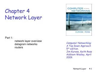
Part 4: Network Layer
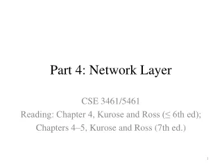
Part 4: Network Layer. CSE 3461/5461 Reading: Chapter 4, Kurose and Ross (≤ 6th ed); Chapters 4–5, Kurose and Ross (7th ed.). Part 4: Outline. Overview and Network Layer Services Data Plane: What’s Inside a Router? Data Plane: Internet Protocol (IP) and Addressing (IPv4, IPv6)

Part 4: Network Layer
E N D
Presentation Transcript
Part 4: Network Layer CSE 3461/5461 Reading: Chapter 4, Kurose and Ross (≤ 6th ed); Chapters 4–5, Kurose and Ross (7th ed.)
Part 4: Outline • Overview and Network Layer Services • Data Plane: What’s Inside a Router? • Data Plane: Internet Protocol (IP) and Addressing (IPv4, IPv6) • Control Plane: Routing Algorithms: Link-State and Distance-Vector • Control Plane: Internet Routing Protocols: • Intra-Domain • Inter-Domain • Control Plane: Multicast and Anycast Routing • Tools of the Trade
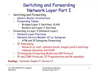
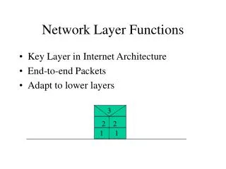
network data link physical network data link physical network data link physical network data link physical network data link physical network data link physical network data link physical network data link physical application transport network data link physical application transport network data link physical Network Layer Functions • Transport packet from sending to receiving hosts • Network layer protocols in every host, router Three important functions: • Switching: move packets from router’s input to appropriate router output • Call setup: some network architectures require router call setup along path before data flows • Path determination: route taken by packets from source to dest. routing algorithms
Two Key Network-Layer Functions Analogy: • Routing: process of planning trip from source to destination • Forwarding: process of getting through single interchange • Forwarding: move packets from router’s input to appropriate router output (data plane) • Routing: determine route taken by packets from source to destination (control plane) • routing algorithms
Routing Algorithm Routing algorithm determines end-end-path through network (control plane) Forwarding table determines local forwarding at this router (data plane) Value in arriving packet’s header 1 0111 2 3 Interplay Between Routing and Forwarding
Connection Setup (Control Plane) • 3rd important function in some network architectures: • ATM, frame relay, X.25 • Before datagrams flow, two end hosts and intervening routers establish virtual connection • Routers get involved • Network vs. transport layer connection service: • Network layer: between two hosts (may also involve intervening routers in case of VCs) • Transport layer: between two processes on end systems
Network Service Model (1) Q: What service model for “channel” transporting datagrams from sender to receiver? Example services for individual datagrams: • Guaranteed delivery • Guaranteed delivery with less than 40 ms delay Example services for a flow of datagrams: • In-order datagram delivery • Guaranteed minimum bandwidth to flow • Restrictions on changes in inter-packet spacing
Network Service Model (2) Q: What service model for “channel” transporting packets from sender to receiver? • Guaranteed bandwidth? • Preservation of inter-packet timing (no jitter)? • Loss-free delivery? • In-order delivery? • Congestion feedback to sender? The most important abstraction provided by network layer: ? virtual circuit or datagram? ? ? Service abstraction
Connection/Connectionless Service • Datagramnetwork provides network-layer connectionlessservice • Virtual-circuit network provides network-layer connectionservice • Analogous to TCP/UDP connection-oriented, connectionless transport-layer services, but: • Service:host-to-host • No choice:network provides one or the other • Implementation:in network core
Virtual Circuits • Call setup, teardown for each call before data can flow • Each packet carries VC identifier (not destination host OD) • Every router on source-dest path s maintain “state” for each passing connection: Transport-layer connection only involved two end systems • Link, router resources (bandwidth, buffers) may be allocated to VC to get circuit-like performance • Multi-protocol label switching (MPLS) is inspired by VCs to implement more flexible routing (details in “link layer” slides) • “Source-to-dest path behaves much like telephone circuit” • Performance-wise • Network actions along source-to-dest path
Application Transport Network Data link Physical Application Transport Network Data link Physical Virtual Circuits: Signaling Protocols • Used to setup, maintain teardown VC • Used in ATM, frame-relay, X.25 • Not used in today’s Internet 6. Receive data 5. Data flow begins 4. Call connected 3. Accept call 1. Initiate call 2. Incoming call
Application Transport Network Data link Physical Application Transport Network Data link Physical Datagram Networks: Internet Model • No call setup at network layer • Routers: no state about end-to-end connections • No network-level concept of “connection” • Packets typically routed using destination host ID • Packets between same source-dest pair may take different paths 1. Send data 2. Receive data
Routing Algorithm 4 billion IP addresses, so rather than list individual destination address list range of addresses (aggregate table entries) IP address in arriving packet’s header 1 0111 2 3 Data Plane: Datagram Forwarding Table (1)
Data Plane: Datagram Forwarding Table (2) Q: But what happens if ranges don’t divide up so nicely?
Longest Prefix Matching Longest Prefix Matching When looking for forwarding table entry for given destination address, use longest address prefix that matches destination address. Examples: Which interface? Dest. Addr.: 11001000 00010111 00010110 10100001 Which interface? Dest. Addr.: 11001000 00010111 00011000 10101010
Network Layer Service Models * Constant bit rate (CBR); variable bit rate (VBR); adaptive bit rate (ABR); uniform bit rate (UBR) • Internet model being extended with differentiated services (DiffServ)
Datagram or VC Network: Why? Internet • Data exchange among computers • “Elastic” service, no strict timing req. • “Smart” end systems (computers) • Can adapt, perform control, error recovery • Simple inside network, complexity at “edge” • Many link types • Different characteristics • Uniform service difficult ATM • Evolved from telephony • Human conversation: • Strict timing, reliability requirements • Need for guaranteed service • “Dumb” end systems • Telephones • Complexity inside network
Part 4: Outline • Overview and Network Layer Services • Data Plane: What’s Inside a Router? • Data Plane: Internet Protocol (IP) and Addressing (IPv4, IPv6) • Control Plane: Routing Algorithms: Link-State and Distance-Vector • Control Plane: Internet Routing Protocols: • Intra-Domain • Inter-Domain • Control Plane: Multicast and Anycast Routing • Tools of the Trade
High-speed switching fabric Router Architecture Overview Two key router functions: • Run routing algorithms/protocol (RIP, OSPF, BGP) • Switching datagrams from incoming to outgoing link Forwarding tables computed, pushed to input ports Routing processor Routing, management control plane (software) Forwarding data plane (hardware) Router input ports Router output ports
Input Port Functions Lookup, forwarding queueing Decentralized switching: • Given datagram destination, lookup output port using forwarding table in input port memory • Goal: complete input port processing at ‘line speed’ • Queueing: if datagrams arrive faster than forwarding rate into switch fabric Link layer protocol (receive) Switch fabric Line termination Physical layer: bit-level reception Data link layer: e.g., Ethernet see chapter 5
Switching Fabrics • Transfer packet from input buffer to appropriate output buffer • Switching rate: rate at which packets can be transferred from inputs to outputs • Often measured as multiple of input/output line rate • N inputs: switching rate N times line rate desirable • Three types of switching fabrics: memory Bus Memory Crossbar
Output port (e.g., Ethernet) Input port (e.g., Ethernet) Memory System bus Switching via Memory First generation routers: • Traditional computers with switching under direct control of CPU • Packet copied to system’s memory • CPU extracts dest address from packet’s header, looks up output port in forwarding table, copies to output port • Speed limited by memory bandwidth (2 bus crossings per datagram) • One packet at a time
Switching via Bus • Datagram from input port memory to output port memory via a shared bus • Bus contention: switching speed limited by bus bandwidth • One packet a time • 32 Gbps bus, Cisco 5600: sufficient speed for access and enterprise routers Bus
Crossbar Switching via Interconnection Network • Forwards multiple packets in parallel • Banyan networks, crossbar, other interconnection nets initially developed to connect processors in multiprocessor • When packet from port A needs to forwarded to port Y, controller closes cross point at intersection of two buses • Advanced design: fragmenting datagram into fixed length cells, switch cells through the fabric. A B C Y Z X
Datagram buffer queueing Output Ports • Buffering required when datagrams arrive from fabric faster than the transmission rate • Scheduling discipline chooses among queued datagrams for transmission Switch fabric Line termination Link layer protocol (send)
Switch fabric Switch fabric One packet time later At t, packets more from input to output Output Port Queueing • Suppose Rswitch is N times faster than Rline • Still have output buffering when multiple inputs send to same output • Queueing (delay) and loss due to output port buffer overflow!
How Much Buffering? • RFC 3439 rule of thumb: average buffering equal to “typical” RTT (say 250 ms) times link capacity C • e.g., C = 10 Gpbs link: 2.5 Gbit buffer • Recent recommendation: with N flows, buffering equal to
switch fabric One packet time later: green packet experiences HOL blocking Input Port Queueing • Fabric slower than input ports combined queuing may occur at input queues • Queuing delay and loss due to input buffer overflow! • Head-of-the-Line (HOL) blocking: queued datagram at front of queue prevents others in queue from moving forward switch fabric Output port contention: only one red datagram can be transferred.Lower red packet is blocked
Part 4: Outline • Overview and Network Layer Services • Data Plane: What’s Inside a Router? • Data Plane: Internet Protocol (IP) and Addressing (IPv4, IPv6) • Control Plane: Routing Algorithms: Link-State and Distance-Vector • Control Plane: Internet Routing Protocols: • Intra-Domain • Inter-Domain • Control Plane: Multicast and Anycast Routing • Tools of the Trade
ICMP protocol • Error reporting • Router “signaling” IP protocol • Addressing conventions • Datagram format • Packet handling conventions Routing protocols • Path selection • RIP, OSPF, BGP Routing table The Internet Network Layer Host, router network layer functions: Transport layer: TCP, UDP Network layer Link layer Physical layer
IPv4 Datagram Format IP protocol version number 32 bits Total datagram length (bytes) Header length (bytes) Type of service Head. len Ver Length For fragmentation/ reassembly Fragment offset “Type” of data Flgs 16-bit identifier Max number remaining hops (decremented at each router) Upper layer Time to live Internet checksum 32 bit source IP address 32 bit destination IP address Upper layer protocol to deliver payload to E.g. timestamp, record route taken, specify list of routers to visit. Options (if any) Data (variable length, typically a TCP or UDP segment) How much overhead? • 20 bytes of TCP • 20 bytes of IP • = 40 bytes + app layer overhead
… … Reassembly IP Fragmentation & Reassembly (1) • Network links have MTU (max. transfer size): largest possible link-level frame • different link types, different MTUs • Large IP datagram divided (“fragmented”) within net • One datagram becomes several datagrams • “Reassembled” only at final destination • IP header bits used to identify, order related fragments Fragmentation: In: 1large datagram Out: 3 smaller datagrams
Length =1500 Length =1500 Length =4000 Length =1040 ID = x ID = x ID = x ID = x Fragflag =0 Fragflag =1 Fragflag =1 Fragflag =0 Offset =0 Offset =370 Offset =185 Offset =0 One large datagram becomes Several smaller datagrams IP Fragmentation & Reassembly (2) Example: • 4000 byte datagram • MTU = 1500 bytes 1480 bytes in data field Offset = 1480/8
223.1.1.2 223.1.2.1 223.1.3.27 223.1.3.1 223.1.3.2 223.1.2.2 IP Addressing: Introduction 223.1.1.1 • IP address: 32-bit identifier for host, router interface • Interface: connection between host, router and physical link • Routers typically have multiple interfaces • Host may have multiple interfaces • IP addresses associated with interface, not host, router 223.1.1.4 223.1.2.9 223.1.1.3 223.1.1.1 = 11011111 00000001 00000001 00000001 223 1 1 1
IP Addressing (1) 223.1.1.1 • IP address: • Network part (high order bits) • Host part (low order bits) • What’s a network?(from IP address perspective) • Device interfaces with same network part of IP address • Can physically reach each other without intervening router 223.1.2.1 223.1.1.2 223.1.2.9 223.1.1.4 223.1.2.2 223.1.3.27 223.1.1.3 LAN 223.1.3.2 223.1.3.1 Network consisting of 3 IP networks (for IP addresses starting with 223, first 24 bits are network address)
223.1.3.27 223.1.3.1 223.1.3.2 IP Addressing (2) 223.1.1.2 223.1.1.1 223.1.1.4 How to find the networks? • Detach each interface from router, host • Create “islands of isolated networks” (subnets) 223.1.1.3 223.1.7.0 223.1.9.2 223.1.9.1 223.1.7.1 223.1.8.1 223.1.8.0 223.1.2.6 Interconnected system consisting of six networks 223.1.2.1 223.1.2.2
multicast address 1110 network host 110 network 10 host IP Addressing: Classes Given notion of “network”, let’s re-examine IP addresses: “Classful” addressing: Class 1.0.0.0 to 127.255.255.255 A network 0 host 128.0.0.0 to 191.255.255.255 B 192.0.0.0 to 223.255.255.255 C 224.0.0.0 to 239.255.255.255 D 32 bits
Host part Network part 11001000 0001011100010000 00000000 200.23.16.0/23 IP Addressing: CIDR • Classful addressing: • Inefficient use of address space, address space exhaustion • e.g., class B net allocated enough addresses for 65K hosts, even if only 2K hosts in that network • CIDR:Classless InterDomain Routing • Network portion of address of arbitrary length • Address format: a.b.c.d/x, where x is # bits in network portion of address
IP Addresses: How to Get One? (1) Hosts (host portion): • Hard-coded by system admin in a file • Windows: Control Panel → Network→ Configuration → TCP/IP → Properties • *nix: /etc/rc.config, /etc/network/interfaces • DHCP:Dynamic Host Configuration Protocol: dynamically get address: “plug-and-play” • Host broadcasts “DHCP discover” msg • DHCP server responds with “DHCP offer” msg • Host requests IP address: “DHCP request” msg • DHCP server sends address: “DHCP ack” msg • DHCP can send system configuration data too
IP Addresses: How to Get One? (2) Network (network portion): • Get allocated portion of ISP’s address space: ISP's block11001000 00010111 00010000 00000000 200.23.16.0/20 Organization 0 11001000 00010111 00010000 00000000 200.23.16.0/23 Organization 1 11001000 00010111 00010010 00000000 200.23.18.0/23 Organization 2 11001000 00010111 00010100 00000000 200.23.20.0/23 ... ….. …. …. Organization 7 11001000 00010111 00011110 00000000 200.23.30.0/23
NAT: Network Address Translation (1) Motivation: local network uses just one IP address as far as outside world is concerned: • Range of addresses not needed from ISP: just one IP address for all devices • Can change addresses of devices in local network without notifying outside world • Can change ISP without changing addresses of devices in local network • Devices inside local net not explicitly addressable, visible by outside world (a security plus)
NAT: Network Address Translation (2) Implementation: NAT router must: • Outgoing datagrams:replace (source IP address, port #) of every outgoing datagram with (NAT IP address, new port #) . . . remote clients/servers will respond using (NAT IP address, new port #) as destination address • Remember (in NAT translation table)every (source IP address, port #) to (NAT IP address, new port #) translation pair • Incoming datagrams:replace(NAT IP address, new port #) in dest fields of every incoming datagram with corresponding (source IP address, port #) stored in NAT table
3 1 2 4 S: 10.0.0.1, 3345 D: 128.119.40.186, 80 S: 138.76.29.7, 5001 D: 128.119.40.186, 80 1:Host 10.0.0.1 sends datagram to 128.119.40.186, 80 2:NAT router changes datagram source addr from 10.0.0.1, 3345 to 138.76.29.7, 5001, updates table S: 128.119.40.186, 80 D: 10.0.0.1, 3345 S: 128.119.40.186, 80 D: 138.76.29.7, 5001 NAT: Network Address Translation (3) 10.0.0.1 10.0.0.4 10.0.0.2 138.76.29.7 10.0.0.3 4:NAT router changes datagram dest addr from 138.76.29.7, 5001 to 10.0.0.1, 3345 3:Reply arrives dest. address: 138.76.29.7, 5001
NAT: Network Address Translation (4) • 16-bit port-number field: • 60,000 simultaneous connections with a single LAN-side address! • NAT is controversial: • Routers should only process up to layer 3 • Violates end-to-end argument • NAT possibility must be taken into account by app designers, e.g., P2P applications • Address shortage should instead be solved by IPv6
NAT Traversal Problem (1) • Client wants to connect to server with address 10.0.0.1 • Server address 10.0.0.1 local to LAN (client can’t use it as destination address) • Only one externally visible NATed address: 138.76.29.7 • Solution 1: statically configure NAT to forward incoming connection requests at given port to server • e.g., (123.76.29.7, port 25000) always forwarded to 10.0.0.1 port 25000 10.0.0.1 client ? 10.0.0.4 138.76.29.7 NAT router
10.0.0.1 IGD NAT router NAT Traversal Problem (2) • Solution 2: Universal Plug and Play (UPnP) Internet Gateway Device (IGD) Protocol. Allows NATed host to: • Learn public IP address (138.76.29.7) • Add/remove port mappings (with lease times) i.e., automate static NAT port map configuration
10.0.0.1 NAT router NAT Traversal Problem (3) • Solution 3: relaying (used in Skype) • NATed client establishes connection to relay • External client connects to relay • Relay bridges packets between to connections 2. Connection to relay initiated by client 1. Connection to relay initiated by NATed host 3. Relaying established client 138.76.29.7
200.23.16.0/23 200.23.18.0/23 200.23.30.0/23 200.23.20.0/23 . . . . . . Hierarchical Addressing: Route Aggregation (1) Hierarchical addressing allows efficient advertisement of routing information: Organization 0 Organization 1 “Send me anything with addresses beginning 200.23.16.0/20” Organization 2 Fly-By-Night-ISP Internet Organization 7 “Send me anything with addresses beginning 199.31.0.0/16” ISPs-R-Us
200.23.16.0/23 200.23.18.0/23 200.23.30.0/23 200.23.20.0/23 Hierarchical Addressing: Route Aggregation (2) Hierarchical addressing allows efficient advertisement of routing information: Organization 0 11001000 00010111 00010000 00000000 Organization 1 “Send me anything with addresses beginning 200.23.16.0/20” 11001000 00010111 00010010 00000000 Organization 2 Fly-By-Night-ISP Internet 11001000 00010111 00010100 00000000 Organization 7 11001000 00010111 00011110 00000000 ISP block: 20 bits
200.23.16.0/23 200.23.18.0/23 200.23.30.0/23 200.23.20.0/23 . . . . . . Hierarchical Addressing: More Specific Routes ISPs-R-Us has a more specific route to Organization 1 Organization 0 “Send me anything with addresses beginning 200.23.16.0/20” Organization 2 Fly-By-Night-ISP Internet Organization 7 “Send me anything with addresses beginning 199.31.0.0/16 or 200.23.18.0/23” ISPs-R-Us Organization 1