Chapter 4 Network Layer
Chapter 4 Network Layer. Part 1: network layer overview datagram networks routers. Computer Networking: A Top Down Approach 5 th edition. Jim Kurose, Keith Ross Addison-Wesley, April 2009. . Chapter 4: Network Layer. Chapter goals: understand principles behind network layer services:

Chapter 4 Network Layer
E N D
Presentation Transcript
Chapter 4Network Layer Part 1: network layer overview datagram networks routers Computer Networking: A Top Down Approach 5th edition. Jim Kurose, Keith RossAddison-Wesley, April 2009. Network Layer
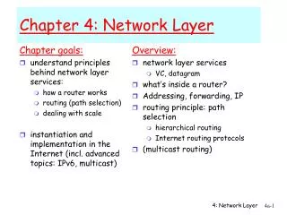
Chapter 4: Network Layer Chapter goals: • understand principles behind network layer services: • network layer service models • forwarding versus routing • how a router works • routing (path selection) • dealing with scale • advanced topics: IPv6, mobility • instantiation, implementation in the Internet Network Layer
4. 1 Introduction 4.2 Virtual circuit and datagram networks 4.3 What’s inside a router 4.4 IP: Internet Protocol Datagram format IPv4 addressing ICMP IPv6 4.5 Routing algorithms Link state Distance Vector Hierarchical routing 4.6 Routing in the Internet RIP OSPF BGP 4.7 Broadcast and multicast routing Chapter 4: Network Layer Network Layer
transport segment from sending to receiving host on sending side encapsulates segments into datagrams on rcving side, delivers segments to transport layer network layer protocols in every host, router router examines header fields in all IP datagrams passing through it network data link physical network data link physical network data link physical network data link physical network data link physical network data link physical network data link physical network data link physical network data link physical network data link physical network data link physical application transport network data link physical application transport network data link physical Network layer Network Layer
Two Key Network-Layer Functions • forwarding: move packets from router’s input to appropriate router output • routing: determine route taken by packets from source to dest. • routing algorithms analogy: • routing: process of planning trip from source to dest • forwarding: process of getting through single interchange Network Layer
routing algorithm local forwarding table header value output link 0100 0101 0111 1001 3 2 2 1 value in arriving packet’s header 1 0111 2 3 Interplay between routing and forwarding Each router has a forwarding table Corresponding value is the output link on which to place the packet Use a value in a packet’s header to index into the table Network Layer
Forwarding table • A routing algorithm is used to configure the table • Algorithm may be centralized and thus each router must download table • Algorithm my be decentralized and run in each router • In either case, router receives routing protocol messages that are used to configure the table Network Layer
routers • Network level (layer 3): packet switch transfers a packet from the input link interface to the output link interface according to a value in a field in the header of the network-layer packet • Link-layer switches (layer 2): base their decision on values in the fields in the link-layer frame. • Routers are network level but must also act as link-layer switch since they are physically connected to another device Network Layer
Connection setup • 3rd important function in some network architectures: • ATM (asynchronous transfer mode), frame relay, X.25 • before datagrams flow, two end hosts and intervening routers establish virtual connection • routers get involved • network vs transport layer connection service: • network: between two hosts (may also involve intervening routers in case of VCs) • transport: between two processes Network Layer
Example services for individual datagrams: guaranteed delivery guaranteed delivery with bounded delay (say less than 40 msecdelay) Example services for a flow of datagrams: in-order datagram delivery guaranteed minimum bandwidth to flow (acts like transport layer): if bit rate is below specified rate, guarantee delivery within specified delay Network service model Q: What service model for “channel” transporting datagrams from sender to receiver? Network Layer
Example services for individual datagrams: guaranteed delivery guaranteed delivery with bounded delay (say less than 40 msecdelay) Example services for a flow of datagrams: guaranteed max jitter. i.e., restrictions on changes in inter-packet spacing security services. Network layer could encrypt the payloads of all datagrams sent to destination host. Source and destination know a secret session key …and other services! Network service model Q: What service model for “channel” transporting datagrams from sender to receiver? Network Layer
Network layer service models: Guarantees ? Network Architecture Internet ATM ATM ATM ATM Service Model best effort* CBR VBR ABR UBR Congestion feedback no (inferred via loss) no congestion no congestion yes no Bandwidth none constant rate guaranteed rate guaranteed minimum none Loss no yes yes no no Order no yes yes yes yes Timing no yes yes no no CBR: constant bit rate ATM network service VBR: variable bit rate ATM network service ABR: available bit rate ATM network service UBR: unspecified bit rate ATM network service * i.e., no service at all! A network that delivered no packets would meet this requirement! Network Layer
ATM networks • Constant bit rate (CBR) ATM network service • Goal: provide a flow of packets (known as cells) with a virtual pipe whose properties are the same as if a dedicated fixed-bandwidth transmissions link existed between source and destination hosts. • Available bit rate (ABR) ATM network service • Slightly-better-than-best-effort-service • Cells may be lost, but cannot be reordered and a minimum transmission rate is guaranteed. • Can provide congestion feedback to transport layer Network Layer
4. 1 Introduction 4.2 Virtual circuit and datagram networks 4.3 What’s inside a router 4.4 IP: Internet Protocol Datagram format IPv4 addressing ICMP IPv6 4.5 Routing algorithms Link state Distance Vector Hierarchical routing 4.6 Routing in the Internet RIP OSPF BGP 4.7 Broadcast and multicast routing Chapter 4: Network Layer Network Layer
Network layer connection and connection-less service • datagram network provides network-layer connectionless service • Used for the internet • VC network provides network-layer connection service • Used for some DSL services • Mostly deployed by telephone companies • Mostly used to access internet today • In 90’s was “next big thing” Network Layer
Network layer connection and connection-less service • VC network is analogous to the transport-layer services, but: • service: host-to-host instead of process-to-process • no choice: network provides connection-oriented or connectionless but cannot provide both • implementation: • in network core (in the routers) • transport-layer connection service is only in the edges (hosts). Network Layer
call setup, teardown for each call before data can flow each packet carries VC identifier (not destination host address) every router on source-dest path maintains “state” for each passing connection link, router resources (bandwidth, buffers) may be allocated to VC (dedicated resources = predictable service) “source-to-dest path behaves much like telephone circuit” performance-wise network actions along source-to-dest path Virtual circuits network-layer connections Network Layer
VC implementation a VC consists of: • path from source to destination (a series of links and routers) • VC numbers, one number for each link along path • entries in forwarding tables in routers along path • packet belonging to VC carries VC number (rather than dest address) • VC number can be changed on each link. • New VC number comes from forwarding table Network Layer
VC number 22 32 12 3 1 2 interface number Incoming interface Incoming VC # Outgoing interface Outgoing VC # 1 12 3 22 2 63 1 18 3 7 2 17 1 97 3 87 … … … … Forwarding table Network decides on path for this VC: A-R1-R2-B and assigns VC numbers 12, 22, 32 to the links. Forwarding table in northwest router: Routers maintain connection state information! Network Layer
Virtual Circuits • Why not keep same VC number for all links? • Replacing the number keeps the VC number field small • VC setup is simplified • Each router can choose a different number • Otherwise would have to coordinate the number across all routers on the path Network Layer
Virtual Circuits • Three phases in VC • VC setup. Network layer software does: • Determines path (series of links and routers) • Determines VC number for each link along path • Adds entry in the forwarding table in each router • May reserve resources along path (e.g., bandwidth) • Data transfer. Packets flow. • VC teardown. Initiated by sender or receiver. • Network informs other side of shutdown • Update forwarding tables of all routers on path Network Layer
used to setup, maintain teardown VC used in ATM, frame-relay, X.25 not used in today’s Internet application transport network data link physical application transport network data link physical Virtual circuits: signaling protocols We’re not covering signaling protocols! 6. Receive data 5. Data flow begins 4. Call connected 3. Accept call 1. Initiate call 2. incoming call Network Layer
no call setup at network layer routers: no state about end-to-end connections no network-level concept of “connection” packets forwarded using destination host address packets between same source-dest pair may take different paths application transport network data link physical application transport network data link physical Datagram networks 1. Send data 2. Receive data Network Layer
Each router still has forwarding table Table only matches destination address to link interface. When packet arrives at router, router uses destaddr to index into the forwarding table & determine output interface Then forwards packet to that interface Table is changed very slowly by a routing algorithm (typically 1-to-5 minutes!) application transport network data link physical application transport network data link physical Datagram networks 1. Send data 2. Receive data Network Layer
Forwarding table Assume 32-bit addresses: 4 billion possible entries That’s a big table! Destination Address RangeLink Interface 11001000 00010111 00010000 00000000 through 0 11001000 00010111 00010111 11111111 11001000 00010111 00011000 00000000 through 1 11001000 00010111 00011000 11111111 11001000 00010111 00011001 00000000 through 2 11001000 00010111 00011111 11111111 otherwise 3 Group addresses Network Layer
Longest prefix matching Prefix MatchLink Interface 11001000 00010111 00010 0 11001000 00010111 00011000 1 11001000 00010111 00011 2 otherwise 3 Examples Which interface? DA: 11001000 00010111 00010110 10100001 Which interface? DA: 11001000 00010111 00011000 10101010 Problem: address may match two or more table entries: the second DA matches both second and third entries Resolution: use the longest match Network Layer
Internet (datagram) data exchange among computers “elastic” service, no strict timing req. “smart” end systems (computers) can adapt, perform control, error recovery simple inside network, complexity at “edge” many link types different characteristics uniform service difficult Easy to implement new application level service: just define new protocol in host devices! ATM (VC) evolved from telephony human conversation: strict timing, reliability requirements need for guaranteed service “dumb” end systems telephones complexity inside network Hard to implement new service: must update every router! Datagram or VC network: why? Network Layer
VC questions • Suppose that routers were subjected to conditions that might cause them to fail fairly often. Would this argue in favor of a VC or datagram architecture? Why? • Suppose that a source node and a destination require that a fixed amount of capacity always be avialable at all routers on the path between the source and destination node, for the exclusive use of traffic flowing between this source and destination node. Would this argue in favor of a VC or datagram architecture? Why? Network Layer
VC questions • Suppose that a VC number is an 8-bit field. What is the maximum number of virtual circuits that can be carried over a link? • Suppose a central node determines paths and VC numbers at a connection setup. Suppose the same VC number is used on each link along the VC’s path (not how it’s really done). Describe how the central node might determine the VC number at connection setup. Is it possible that there are fewer VCs inprogress than the max yet there is no common free VC number? • A bare-bones forwarding table in a VC network has four columns. What is the meaning of the values in each of these columns. A bare-bones forwarding table in a datagram network has two columns. What is the meaning of the values in each of these columns? Network Layer
4. 1 Introduction 4.2 Virtual circuit and datagram networks 4.3 What’s inside a router 4.4 IP: Internet Protocol Datagram format IPv4 addressing ICMP IPv6 4.5 Routing algorithms Link state Distance Vector Hierarchical routing 4.6 Routing in the Internet RIP OSPF BGP 4.7 Broadcast and multicast routing Chapter 4: Network Layer Network Layer
Router Architecture Overview Forwarding is the same as switching Two key router functions: • run routing algorithms/protocol (RIP, OSPF, BGP) • forwarding datagrams from incoming to outgoing link forwarding Data plane (hardware) Routing management Control plane (software) Network Layer PCI bus from processor to input ports
Routing processor • Executes routing protocols • Maintains routing tables and attached link state information • Computes the forwarding table for the router • Performs network management functions. • These functions operate at the millisecond or second timescale, so can be implemented in software Network Layer
Router forwarding plane • The input ports, output ports, and switching fabric together are implemented in hardware and are called the router forwarding plane • why implement these functions in hardware? • 10Gbps input link, 64-byte IP datagram • Input link has 51.2ns to process the datagram before another one arrives • If N input ports are on a line card (common), must operate N times faster Network Layer
Input Port Functions Decentralized switching: • given datagram dest., lookup output port using forwarding table in input port memory • Network control packets sent to the processor • goal: complete input port processing at ‘line speed’ • queuing: if datagrams arrive faster than forwarding rate into switch fabric Physical layer: bit-level reception Data link layer: e.g., Ethernet see chapter 5 Note: port here is a physical port. Different from the software ports used with sockets. Network Layer
Input Port Functions • Input ports have small memory to contain forwarding table (uses cache) • Output port lookup must be very fast; linear search is too slow! • Packet may have to be queued if switching fabric is busy • Other actions • Physical and link-layer processing • Packet’s version number, checksum and time-to-live fields must be checked and latter two rewritten • Counters used for network management (e.g., number of datagrams received) must be updated. Network Layer
Three types of switching fabrics Network Layer
Memory Input Port Output Port System Bus Switching Via Memory First generation routers: • traditional computers with switching under direct control of CPU • packet copied to system’s memory • speed limited by memory bandwidth (2 bus crossings per datagram) Single bus/input/output port limits throughput Network Layer
Switching Via a Bus • datagram from input port memory to output port memory via a shared bus (processor not used) • Input port pre-pends an internal header to indicate output port • Label removed at output port before sending • bus contention: switching speed limited by bus bandwidth; only one packet can be on bus at a time • 32 Gbps bus, Cisco 5600: sufficient speed for access and enterprise routers Network Layer
Switching Via An Interconnection Network • overcome bus bandwidth limitations • Banyan networks, other interconnection nets initially developed to connect processors in multiprocessor • All input ports have lines to all output ports • Switching fabric can selectively open connections • Still possible to have contention: two input ports trying to connect to the same output port • advanced design: fragmenting datagram into fixed length cells, switch cells through the fabric. • Cisco 12000: switches 60 Gbps through the interconnection network Network Layer
Output Ports • Buffering required when datagrams arrive from fabric faster than the transmission rate • Scheduling discipline chooses among queued datagrams for transmission Network Layer
Output port queueing • buffering when arrival rate via switch exceeds output line speed • queueing (delay) and loss due to output port buffer overflow! Network Layer
. RTT C N How much buffering? • RFC 3439 rule of thumb*: average buffering equal to “typical” RTT (say 250 msec) times link capacity C • e.g., C = 10 Gps link: 2.5 Gbit buffer • Recent recommendation**: with N flows, buffering equal to *based on an analysis of queueing dynamics of a relatively small number of TCP flows (Villamizar 1994) **based on theoretical and experiments on large flows (Appenzeller 2004) Network Layer
Input Port Queuing • Fabric slower than input ports combined -> queueing may occur at input queues • Head-of-the-Line (HOL) blocking: queued datagram at front of queue prevents others in queue from moving forward • queueing delay and loss due to input buffer overflow! Can occur when packet arrival rate reaches 58% of capacity! There are solutions…beyond the scope of this class! Network Layer