Download
1 / 10
100 likes | 289 Views
The 741 Operational Amplifier. Mr J Robinson. The 741 Op-amp

E N D
The 741 Operational Amplifier Mr J Robinson
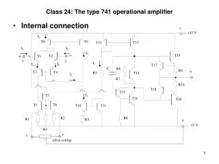
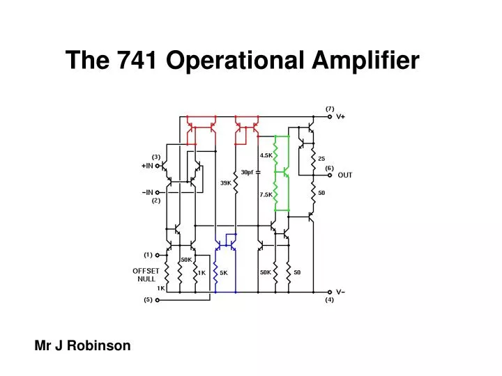
The 741 Op-amp The most common and most famous op-amp is the mA741C or just 741, which is packaged in an 8-pin mini-DIP. The integrated circuit contains 20 transistors and 11 resistors. Introduced by Fairchild in 1968, the 741 and subsequent IC op-amps including FET-input op-amps have become the standard tool for achieving amplification and a host of other tasks.
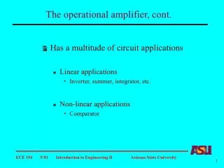
Some of the general characteristics of the IC version are: • High gain, on the order of a million • High input impedance, low output impedance • Used with split supply, usually +/- 9V
Differential Amplifier The 741 will amplify the difference between two inputs with a gain of 100,000 to 1. This makes it a very useful tool in sensing circuits. 1. Temperature low-green light on 741 Op Amp Crocodile Clips Model
Differential Amplifier As the temperature increases the value of the thermister changes. The 741 amplifies this change and the polarity of the output swaps thus switching the red L.E.D. on 2. Temperature high – red light on. 741 Op Amp Crocodile Clips Model
Try this circuit on Crocodile Clips (741 temperature sensor)
Output from a 741 A 741 only can drive a LED as it outputs only around 10 milliamps. A buffering device must be used to allow the control signal to drive a power output. Light-beam alarm. Break the beam and….
The alarm sounds. A latching circuit would be needed if the alarm was to be permanently on until reset.
Try this circuit on Crocodile Clips (sensor with buzzer)