The operational amplifier, cont.
160 likes | 189 Views
Understand the versatility of operational amplifiers in linear and non-linear applications, like inverter and comparator circuits. Learn to design circuits and explore components like thermistors, photoconductors, and transistors. Hands-on projects include building a Dark Activated Switch.

The operational amplifier, cont.
E N D
Presentation Transcript
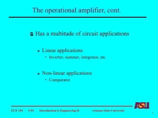
The operational amplifier, cont. • Has a multitude of circuit applications • Linear applications • Inverter, summer, integrator, etc. • Non-linear applications • Comparator
Classwork #2 Find vo
Op amp non-linear applications The output voltage is a function of the input voltage difference Op amp can be forced to work in the linear region with feedback Without feedback, the operation is quite different
The comparator • A comparator is a circuit that monitors two input voltages • One is called the reference voltage, and the other the input voltage • The output voltage depends upon the relation between the reference voltage and the input voltage, i.e., whether Vin is larger or smaller than Vref • Op amps operated without feedback can act as comparators
Comparator Reference voltage to positive input Reference voltage to negative input
Comparator circuits Physical outputs Physical signals
Generic comparator circuit Physical and electrical outputs Physical and electrical input signals
Comparator circuits What are RA and RB? Circuit components that convert physical signals to electrical signals by having electrical properties that change with external physical changes. Examples: Thermistors - temperature sensitive resistors Photoconductors - light sensitive resistors Strain gauges - strain sensitive resistors Microphones - sound sensitive components
Comparator circuits Output component examples LEDs driven by op amp output Power transistor stages to drive LEDs, buzzers, relays Other amplifier stages Voltage to frequency converters Analog to digital converters Multimeters Motors Timers, clocks, recorders
Additional circuit components Diode Variable resistor = RV = R1 + R2
Additional circuit components Bipolar junction transistor Transistor Field effect transistor FET ID = IS IC ≈ IE Large current (VG > 0) Large current (IB > 0) ID IC Zero (VG = 0) Zero (IB = 0)
Additional circuit components Relay Sensing resistor Electromechanical device - a small current is used to control a large current R = R(Temperature) R = R(Pressure) R = R(Light)
Example comparator circuit Light activated switch LED is on when input is below Vref Resistance of photoconductor decreases when illuminated
Classwork Building upon ideas from previous circuit, design a Dark Activated Switch
Classwork Build and test this circuit - use a voltmeter to measure voltages in circuit