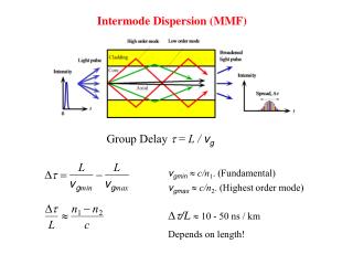
Intermode Dispersion (MMF)
Intermode Dispersion (MMF). Group Delay = L / v g. v gmin c/n 1 . (Fundamental) v gmax c/n 2 . (Highest order mode). D t /L - 50 ns / km Depends on length!. Intramode Dispersion (SMF). Dispersion in the fundamental mode. Group Delay = L / v g

Intermode Dispersion (MMF)
E N D
Presentation Transcript
Intermode Dispersion (MMF) Group Delay = L / vg vgminc/n1. (Fundamental) vgmaxc/n2. (Highest order mode) Dt/L - 50 ns / km Depends on length!
Intramode Dispersion (SMF) Dispersion in the fundamental mode Group Delay = L / vg Group velocityvg depends on Refractive index = n(l) Material Dispersion V-number= n(l) Waveguide Dispersion = (n1n2)/n1 = (l) Profile Dispersion
Material Dispersion All excitation sources are inherently non-monochromatic and emit within a spectrum ∆l of wavelengths. Waves in the guide with different free space wavelengths travel at different group velocities due to the wavelength dependence of n1. The waves arrive at the end of the fiber at different times and hence result in a broadened output pulse. Dm = material dispersion coefficient, ps nm-1 km-1
Waveguide Dispersion Waveguide dispersion: The group velocity vg(01) of the fundamental mode depends on the V-number which itself depends on the source wavelength even if n1 and n2 were constant. Even if n1 and n2 were wavelength independent (no material dispersion), we will still have waveguide dispersion by virtue of vg(01) depending on V and V depending inversely on . Waveguide dispersion arises as a result of the guiding properties of the waveguide which imposes a nonlinear -lm relationship. Dw = waveguide dispersion coefficient Dwdepends on the waveguide structure, ps nm-1 km-1
Chromatic Dispersion Material dispersion coefficient (Dm) for the core material (taken as SiO2), waveguide dispersion coefficient (Dw) (a = 4.2 mm) and the total or chromatic dispersion coefficient Dch (= Dm + Dw) as a function of free space wavelength, l Chromatic = Material + Waveguide
Polarization Dispersion n different in different directions due to induced strains in fiber in manufacturing, handling and cabling. n/n< 10-6 Dpol = polarization dispersion coefficient Typically Dpol = 0.1 - 0.5 ps nm-1 km-1/2
Self-Phase Modulation Dispersion : Nonlinear Effect At sufficiently high light intensities, the refractive index of glass n is n = n + CI where C is a constant and I is the light intensity. The intensity of light modulates its own phase. For Dt1 ps km-1 Imax 3 W cm-2. Dn is 310-7. 2a 10 m, A 7.8510-7 cm2. Optical power 23.5 W in the core
Zero Dispersion Shifted Fiber Total dispersion is zero in the Er-optical amplifier band around 1.55 mm Zero-dispersion shifted fiber Disadvantage: Cross talk (4 wave mixing)
Nonzero Dispersion Shifted Fiber For Wavelength Division Multiplexing (WDM) avoid 4 wave mixing: cross talk. We need dispersion not zero but very small in Er-amplifer band (1525-1620 nm) Dch = 0.1 - 6 ps nm-1 km-1. Nonzero dispersion shifted fibers
Nonzero Dispersion Shifted Fiber Nonzero dispersion shifted fiber (Corning) Fiber with flattened dispersion slope
Dispersion Flattened Fiber Dispersion flattened fiber example. The material dispersion coefficient (Dm) for the core material and waveguide dispersion coefficient (Dw) for the doubly clad fiber result in a flattened small chromatic dispersion between l1 and l2.
Dispersion and Maximum Bit Rate Return-to-zero (RTZ) bit rate or data rate. Nonreturn to zero (NRZ) bit rate = 2 RTZ bitrate
Dispersion and Maximum Bit Rate Maximum Bit Rate Dispersion Bit Rate = constant inversely proportional to dispersion inversely proportional to line width of laser (single frequency lasers!)
Relationships between dispersion parameters, maximum bit rates and bandwidths. RZ = Return to zero pulses. NRZ = Nonreturn to zero pulses. B is the maximum bit rate for NRZ pulses. Example: Bit rate and dispersion Consider an optical fiber with a chromatic dispersion coefficient 8 ps km-1 nm-1 at an operating wavelength of 1.5 m. Calculate the bit rate distance product (BL), and the optical and electrical bandwidths for a10 km fiber if a laser diode source with a FWHP linewidth 1/2 of 2 nm is used. Solution For FWHP dispersion, 1/2/L = |Dch|1/2 = (8 ps km-1 nm-1)(2 nm) = 16 ps km-1 Assuming a Gaussian light pulse shape, the RTZ bit rate distance product (BL) is BL = 0.59L/t1/2 = 0.59/(16 ps km-1) = 36.9 Gb s-1 km. The optical and electrical bandwidths for a 10 km distance is fop = 0.75B = 0.75(36.9 Gb s-1 km) / (10 km) = 2.8 GHz. fel = 0.70fop = 1.9 GHz.
Combining intermodal and intramodal dispersions Consider a graded index fiber with a core diameter of 30 m and a refractive index of 1.474 at the center of the core and a cladding refractive index of 1.453. Suppose that we use a laser diode emitter with a spectral linewidth of 3 nm to transmit along this fiber at a wavelength of 1300 nm. Calculate, the total dispersion and estimate the bit-ratedistance product of the fiber. The material dispersion coefficient Dm at 1300 nm is 7.5 ps nm-1 km-1. How does this compare with the performance of a multimode fiber with the same core radius, and n1 and n2? Solution The normalized refractive index difference = (n1n2)/n1 = (1.4741.453)/1.474 = 0.01425. Modal dispersion for 1 km is intermode = Ln1D2/[(20)(31/2)c] = 2.910-11 s 1 or 0.029 ns. The material dispersion is Dt1/2 = LDm D1/2 = (1 km)(7.5 ps nm-1 km-1)(3 nm) = 0.0225 ns Assuming a Gaussian output light pulse shaper, intramode = 0.4251/2 = (0.425)(0.0225 ns) = 0.0096 ns Total dispersion is B = 0.25/rms = 8.2 Gb
Comparison of typical characteristics of multimode step-index, single-mode step-index, and graded-index fibers. (Typical values combined from various sources; 1997
Dispersion Compensation Total dispersion = DtLt + DcLc = (10 ps nm-1 km-1)(1000 km) + (100 ps nm-1 km-1)(80 km) = 2000 ps/nm for 1080 km or 1.9 ps nm-1 km-1
Dispersion Compensation and Management • Compensating fiber has higher attenuation. Doped core. Need shorter length • More susceptible to nonlinear effects. Use at the receiver end. • Different cross sections. Splicing/coupling losses. • Compensation depends on the temperature. • Manufacturers provide transmission fiber spliced to inverse dispersion fiber for a well defined D vs. l
Dispersion Managed Fiber The inverse dispersion slope of dispersion managed fiber cancels the detrimental effect of dispersion across the a wide spectrum of wavelength. More DWDM channels expected in ultralong haul transmission. (Courtesy of OFS Division of Furukawa.)
Attenuation Attenuation = Absorption + Scattering Attenuation coefficient is defined as the fractional decrease in the optical power per unit distance. a is in m-1. Pout = Pinexp(L)
Rayleigh Scattering Rayleigh scattering involves the polarization of a small dielectric particle or a region that is much smaller than the light wavelength. The field forces dipole oscillations in the particle (by polarizing it) which leads to the emission of EM waves in "many" directions so that a portion of the light energy is directed away from the incident beam. = isothermal compressibility (at Tf) Tf = fictive temperature (roughly the softening temperature of glass) where the liquid structure during the cooling of the fiber is frozen to become the glass structure
Example: Rayleigh scattering limit What is the attenuation due to Rayleigh scattering at around the = 1.55 m window given that pure silica (SiO2) has the following properties: Tf = 1730°C (softening temperature); T = 710-11 m2 N-1 (at high temperatures); n = 1.4446 at 1.5 m. Solution We simply calculate the Rayleigh scattering attenuation using aR = 3.27610-5 m-1 or 3.27610-2 km-1 Attenuation in dB per km is dB = 4.34R = (4.34)(3.73510-2 km-1) = 0.142 dB km-1 This represents the lowest possible attenuation for a silica glass core fiber at 1.55 m.
Corning low-water-peak fiber has no OH- peak E-band is available for communications with this fiber [Photonics Spectra, April 2002 p.69]
Bending loss for three different fibers. The cut-off wavelength is 1.2 mm. All three are operating at = 1.5 mm. Example: Microbending loss It is found that for a single mode fiber with a cut-off wavelength c = 1180 nm, operating at 1300 nm, the microbending loss reaches 1 dB m-1 when the radius of curvature of the bend is roughly 6 mm for = 0.00825, 12 mm for = 0.00550 and 35 mm for = 0.00275. Explain these findings? Solution: Maybe later?