Nano-fluidic Characterization
Nano-fluidic Characterization. Team Members: David Sharp, Davis West, Justin Davis. Project Description. Nano-porous membranes are ideally used as a medicinal filters. Can be used for nano -device manufacturing

Nano-fluidic Characterization
E N D
Presentation Transcript
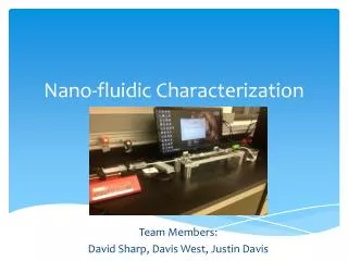
Nano-fluidic Characterization Team Members: David Sharp, Davis West, Justin Davis
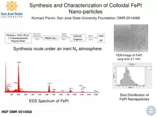
Project Description Nano-porous membranes are ideally used as a medicinal filters. Can be used for nano-device manufacturing Main objective is to build apparatus to measure characteristics of nano-porous membranes Characteristics include pressure differences, fluid flow and average temperature. *SEM Photograph of a Nano-porous membrane
Concept Summary Pressure between pores represents the pressure between whole membrane As flow through membrane increases, pressure difference also increases Varying pore diameter exponentially increases pressure difference
System Architecture • All sensors connected to computer through USB • All sensor values read on LabVIEW • Pressure transducers connected through DAQ device • Signal calibrated to read pressure values instead of voltage • Thermocouple connected with USB converter • Drivers for Flow sensor used to read values on LabVIEW
System Design Pressure Transducers Syringe Pump Flow Sensor Thermocouple Membrane Holder
System Breakdown Continued… Consists of various couplings and fittings to maintain pipe diameter Each sensor is fastened securely to the frame Membrane holder located at center of system Pressure Transducer on both sides of membrane holder Thermocouple placed near end of system Flow Sensor at end to validate pump flow System elevated to keep flow level
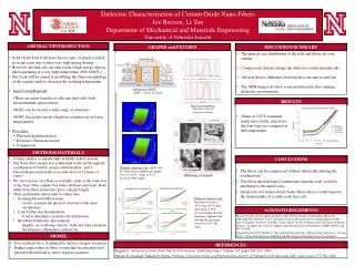
Project Evaluation • System is able to successfully read pressure and flow values through the system • Results found show that each membrane has a slightly higher or lower pressure difference for each flow rate • Due to the membrane pore diameters being slightly different than the true values • Average difference between calculated and experimental values is slight
Future Opportunities • Clear membrane better integrated for higher pressure readings. • Height of system more adjustable • LabVIEW synchronized with syringe pump • Would start as soon as the program began taking measurements, • Setting changes on the front panel
A Special Thanks to Our Sponsors Dr. Michael Schrlau (ME Department) MasoudGolshadi - PhD Student Michael Zona(Xerox) - Industry Guide John Wellin (ME Department) - Guide