Optimization of Transmitter Performance for Accurate Time Calibration and Geolocation
170 likes | 280 Views
This document outlines the findings from the LORIPP Meeting #2 held in Portland, OR, discussing tasks surrounding transmitter calibration to USNO-UTC, transmission performance metrics, and the modeling of GPS timing systems. Key topics include the determination of error thresholds, monitoring requirements, and analysis of transmitted ECD and blink rates. Future plans encompass refining synchronization definitions and examining secondary offsets in Time of Transmission Monitoring (TOTM). The objective is to improve calibration processes and signal accuracy for legacy receivers.

Optimization of Transmitter Performance for Accurate Time Calibration and Geolocation
E N D
Presentation Transcript
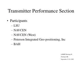
Transmitter Performance Section • Participants • LSU • NAVCEN • NAVCEN (West) • Peterson Integrated Geo-positioning, Inc • BAH LORIPP Meeting #2 Portland, OR September 23-24, 2002
Tasking from LORIPP Meeting 1 • TOTM calibration to USNO-UTC • ABS threshold and time to blink from onset to fault, P(OOT w/o blink) • Determine transmitted ECD and blink if OOT. • Monitor requirements at transmitter and what certification requirements on monitors. • Chain Operations (TOE verses SAM)
LRP Status • NSSX sites • LSU • LORSTA George, WA • LORSTA Narrow Cape, AK • LORSTA Dana, IN • SLEP • TFE • MOD 5 • Delivery Feb 03
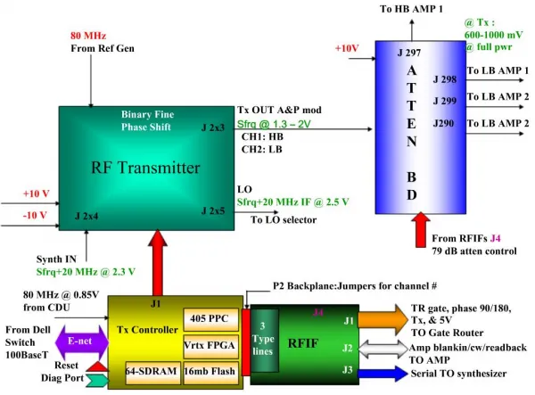
TOT Measurement System Temporary for calibration Ethernetto LSU Antenna current transformers Digital Averaging O’scope USB Computer Temporary at antenna base RS-232 TrueTime XLDC GPS Timing Rcvr Event Time Input Envelope Trigger Circuitry Permanent
Standard Zero Crossing Strobe from Envelope Trigger Start of Pulse
Zero Crossing @ Oscilloscope Zero Crossing @ Transformer Time read from GPS receiver Start of pulse @ Antenna Delay: Transformer to Oscilloscope (148ns) 30 usec Delay GPS to O’scope (15ns) Oscilloscope Measurement (15.54us) Calibration value = 30 + 15.54 + 0.148 – 0.015 = 45.673 us Example of Calibration (data is for Carolina Beach)
Note: 8970M (Dana) off by –0.9 usec per USCG TOTM and approx. 0 per USNO. Note: 8290M (Havre) off by 2.3usec per USCG TOTM and 0.1 usec per USNO.
Pulse Analysis System Pentium PC w/ICS-650 (12 bit) or ICS-652 (14 bit) Antenna Current Transformer • Prototype developed & tested at Baudette 9/05/02 • 800 MHz P3, ICS-650 • Logged TOT, ECD, and Amplitude of each pulse, no raw RF data • Processed 2/3 of the PCI’s (one rate only) • Will continue development on 2 GHz P4 w/ICS-652, log raw RF
Note: Outliers indicate need to log raw RF and visually verify why
Future Plans • Visit to Seneca 8-10 Oct w/DCN (funded by NELS) • Effort to get common, worldwide, definition of what is meant by sync to UTC (presently 2.5 usec offset between USCG and NELS) • Visit to Boise City • Test new pulse analysis system • 2 usec Offset between USCG TOTM and USNO data • Visit to Dana • Long transmission line to resolve sign of delay term • Installation at what other secondaries? • TFE installation starts in Mar 03 in SEUS and will be about 1/month. Do we need the data now? • Gillette, Las Cruces, Searchlight, Middletown, etc. • Canada? • Have about 4 more GPS receivers available, do we procure more?
Conclusions • TOTM system works well and is getting valuable data • I have long felt that large secondary offsets in TOT may be due to offsets between published and actual emission delays • Hence a need for minimum of 12 months of data to establish new values to avoid large position jumps in legacy receivers when going to TOT control. • Getting this data now may enable earlier transition to TOT control • Large offsets may be in master TOT and new emission delays may be unnecessary