Download
1 / 32
320 likes | 445 Views
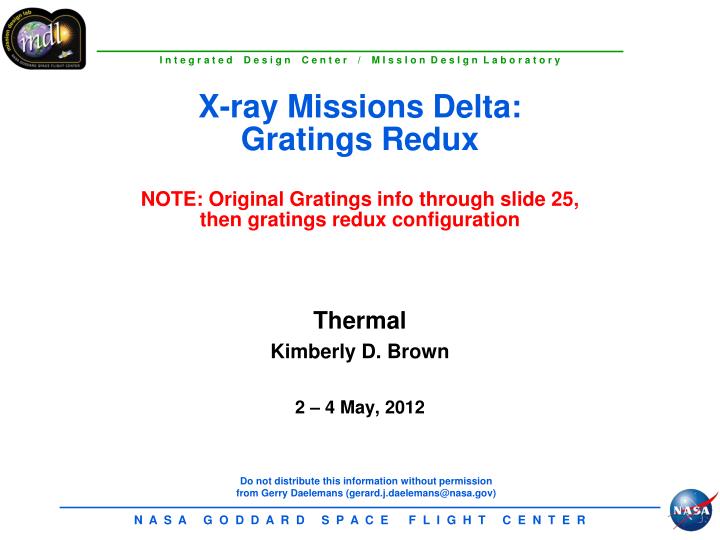
X-ray Missions Delta: Gratings Redux NOTE: Original Gratings info through slide 25, then gratings redux configuration. Thermal Kimberly D. Brown 2 – 4 May, 2012. S/C Bus Thermal Control Subsystem Functional Block Diagram. Thrusters. RW. RW. RW. RW. RWE. RWE. RWE. RWE.

E N D
X-ray Missions Delta:Gratings ReduxNOTE: Original Gratings info through slide 25,then gratings redux configuration Thermal Kimberly D. Brown 2 – 4 May, 2012
S/C Bus Thermal Control Subsystem Functional Block Diagram Thrusters RW RW RW RW RWE RWE RWE RWE Battery (Li-Ion) Radiators Reject Waste Heat to Space FMA PSE Comm System Avionics Gyro Propellant Tanks, Lines and Fill-and-Drain Valves Radiators MLI Thermostatically controlled heaters
Thermal Summary for Instrument • FMA is cold biased and has active heater control via heater controllers • Primary and redundant heater circuits • Same heater circuit for operational and survival (10°C for lower set point for survival) • FMA is thermally isolated from S/C bus • 24 interface mounting points • CCHPs heat pipe internal to FMA to spread heat • FMA internal MLI • Radiator for XGS DPA and DEA • Radiator located on anti-sun side • Heat pipes to transfer heat to radiator panel • S/C provides survival heater power for Instrument Electronics • Kapton film heaters • Prime and redundant heaters per circuit • Two thermostats in series per circuit
Thermal System Summary for S/C Bus • S/C bus is thermally isolated from FMA (24 mounting points) • Insulated MLI on exterior s/c bus, metering structure, backside of Solar Array, non-cell area on front side of Solar array • 15 layer make-up • Silver conductive composite coating ITO/SiOx/Al203/Ag • Low absorptance (0.08 at BOL) and high emittance 0.6 • Radiator Panel for Bus (located on anti-sun side) • Coating NS43G yellow paint • High emittance 0.9 • Heat Pipes • Transfer heat from boxes to radiator panel • Heat pipes embedded in radiator panel to spread heat • Heater Control for Propulsion, Gimbals, Battery, Star Trackers • Mechanical thermostats (operational and survival) • Primary and redundant heater circuits • Two thermostats in series per circuit • Kapton film heaters attached to components
Mission Requirements Orbit parameters – L2- 800,000 km Launch Vehicle – Falcon 9 Launch date – June 2021 Mission Lifetime – 3 yr /5 year goal Mass estimate – payload: 198 kg (Instrument) 245 kg (X-Ray Mirror) – 442 kg total mission: Not available Power estimate – payload: 222 W (Instrument) , 213 W (X-Ray Mirror) – 435 W total Mission class – B Disposal plans – None Needed at L2 (MDL to confirm)
Thermal Driving Requirements • Temperature requirements for Instrument Electronics DEA and DPA • Operational -40°C to 50°C • Survival -55°C to 60°C survival • Need to size a radiator for the following: • DEA 84 watts • DPA 20 Watts • 104 Watt load radiator size is about 0.45 m2 • Sized survival heaters for DEA and DPA • Estimate 23 Watts for DEA and 6 Watts for DPA • Total 29 Watts to maintain at -45°C • FMA heater power of 213 Watts is budget on Instrument side (to maintain +20°C ± 0.5°C) • Re-Size radiator for spacecraft bus • Spacecraft heater power updating from AXSIO • Check 96°C solar array temperature from AXSIO
Spacecraft Temperature Limits • Propulsion System • +10°C to 40˚C • S/C Components Electronics • -10°C to +40°C operational and -20°C to +50°C survival • Avionics, comm system • Solar Array Temperature - Operational -100°C to +106°C (10 C above predict) • CommSystem: • HGA, two axis Gimbal motors 0°C to 40°C • Antenna Dish -40°C to 65°C • Xband: Operational +10°C to 40°C • Li Ion Battery Temperatures - Operational 0°C to +30°C
MEL to Include • CCD Radiator sized for Instrument (not S/C MEL) • Spacecraft thermal MEL needs to include the following for Instrument: • Need to provide radiator for 104 Watts of for DEA and DPA • Size heat pipes from Instrument Boxes to radiator • Provide survival heaters for Instrument electronics during safehold • Budget FMA Interior MLI • FMA heat pipes for mount interface
FMA Thermal Control • 213 Watts, heater controlled • to 20°C±0.5°C Operational heaters (representative locations)
S/C Bus Thermal Control For FMA MLI on interior to radiatively isolate from FMA CCHP isothermalizes mounting interfaces for FMA (redundancy not shown) CCHP embedded in honeycomb radiator panel for spacecraft load
Radiator Locations CCD Radiator Instrument Radiator for Electronics Spacecraft Radiator
Propulsion Subsystem SchematicAXSIO to X-Ray Grating MLI tanks Mechanical thermostats Heater control for all Propulsion components N2 N2H4 N2 N2H4 N2 N2H4 P P P Diaphragm Tanks Eliminated form AXSIO F 22 N Thrusters 4 N Thrusters FD Valves Pressure Transducer Filter Latch Valve F P
Propulsion System Thermal Design • Tank (2) • Conductively isolated tanks from Bus structure with isolation like aluminum support struts • Radiatively isolated by blanketing the tanks (6 layer) inside the S/C bus with a low emittance coating • Bottom deck covered with MLI blanket (15 layer) • Heaters for tanks thermostatically controlled, prime and redundantheaters with mechanical thermostats • Fuel Line Design • Fuel Lines assumed to be internal from tank to thrusters • All lines wrapped with heater elements spirally wrapped • Heaters are thermostatically controlled • All lines spirally wrapped with 5 mil aluminum tape with 50 % overwrap • Lines to be low ε taped then wrapped with MLI sleeve blanketing (15 layer) external • Zonal heaters • Thrusters (4) 1 lbf (4N) • Heaters thermostatically controlled • Prime heater per thruster with two mechanical thermostats per circuit • Thruster has MLI boot blanket cap with over-temperature outer layer for soak back • Current Heater Power Estimate for Propulsion 20.4 Watts
Spacecraft Total * Operational heater circuits
Summary of Radiator Sizes s/c radiator based on 413 Power Watt load Updated in study this week
Radiators Sized for Mission S/C Radiator DEA and DPA CCD Radiator on top
Verification of Thermal System • Perform Thermal Vacuum Thermal Balance Testing Per GEVS at System level. • Perform 4 Hot/Cold Thermal Vacuum Cycles • Perform Thermal Balance Tests Subjecting X-Ray Gratings to Worst Hot and Cold Case Conditions. • Verify Thermal Models, Perform Model Correlation to Test Data. • Verify Proper Operation and Design of Heater Circuits • Verify Proper Thermistor Calibration, Operation and Placement • Verify FMA Interface to S/C Interface • CCHP for Instrument and Spacecraft • Conduct detail TB tests for Spacecraft Bus during Observatory level testing. • Component Level Testing Shall be Performed by the Vendor Prior to Shipment to S/C Vendor: • Heaters, Thermostats, Thermistors • Electronic boxes test 8 hot/cold TV cycling • Instruments test 8 hot/cold TV cycles. • Each Instrument conduct TV qualification and TB testing during instrument level testing of FMA and CCDs. • S/A deployment.
CAT Effects Report • Reduction of Mass savings: • Electronic Instrument Radiator sizing ~1.0 kg • MLI on backside of radiator minimal savings • Reduction of Mass savings : • Front side of array used for shielding ~0.5 kg • Reduction of Instrument survival heater power: • Reduced by ~7 Watts (survival mode only) • No hardware impacts
Future Work • Analyze the thermal effects of solar array as a sunshield on FMA mirror temperature gradient • Analyze the metering structure heater power required – this is driven by Instrument +20°C ± 0.5°C • STOP analysis for thermal-structural distortion requirement for FMA
Issues • Instrument Radiators must be above CCHP evaporators to make CCHPs testable in reflux mode during ground testing • S/C providing thermal hardware to instrument • Interchange of models defined early • ICD well defined
Conclusion • Thermal design meets the mission requirements • Thermal Hardware TRL 9s
Thermal Driving Requirements (changes in red) • Temperature requirements for Instrument Electronics DEA and DPA • Operational -40°C to 50°C • Survival -55°C to 60°C survival • Need to size a radiator for the following: • DEA 42 watts • DPA 20 Watts • RIU 6.3 Watts • 62.0 Watt load radiator size is about 0.25 m2 • Sized survival heaters for DEA and DPA • Estimate 12 Watts for DEA and 6 Watts for DPA • Total 18 Watts to maintain at -45°C • FMA heater power is budget on Instrument side (to maintain +20°C ± 0.5°C) • Re-Size radiator for spacecraft bus
DELTA’s for X-Ray Gratings Redux • MLI Surface Area Reduction: • MLI for metering structure reduced (7 m to 4 m) reduction in surface area • Bow tie for FMA smaller surface area than the circular FMA (MLI reduced for internal MLI) to isolate the FMA from the spacecraft bus. • Added Kevlar for the anti sun Propulsion MLI enclosure • Radiators for Instrument and Spacecraft: • Resized the Instrument Radiator • Placed radiator as close to boxes to reduce heat strap lengths. • Replaced heat pipes with heat straps to reduce cost • Heat strap routing is not layout probably to show the heat transport • S/C radiator 1.3 m2 based on 398 Watts (no change small difference from 413 Watts) • Radiator location defined for this mission. • Component Resizing or Removed:One less tank than precious mission. (less MLI but because there is no structure enclosure around tanks, then need full layer make-up MLI. So the Delta kg is a wash.
Instrument Deck Layout RIU CAMERA(2) DEA Radiator SUN SHIELD Heat straps DPA
FMA Thermal Isolation MLI around FMA “bow tie” Heat Pipes
Future Work • Thermal analysis to determine if heat pipes are required for the spacecraft. • Based on previous missions, it’s possible this mission can be passive for the Spacecraft. • Determine if Instrument Electronics can radiate off box itself instead of heat strap over to radiator design.