Download
1 / 29
290 likes | 419 Views
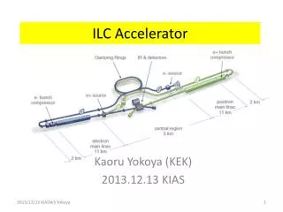
GaAs:Cr detector testing for FCAL calorimeter at planned linear accelerator ILC . V. Elkin, U.Kruchonak. XVI научная конференция молодых учёных и специалистов ОМУС 20 12. The International Linear Collider ILC. ~ 30 km. Parameters of the ILC:

E N D
GaAs:Cr detector testing for FCAL calorimeter at planned linear accelerator ILC V. Elkin, U.Kruchonak XVI научная конференция молодых учёных и специалистов ОМУС 2012
The International Linear Collider ILC ~ 30 km Parameters of the ILC: • e+e- accelerator, sc cavities, gradient 31.5 MV/m => 30km long • CMS energy: 200 to 500 GeV (possible upgrade to 1 TeV) • One interaction region, beam crossing angle of 14mrad and two detectors („push-pull“ scenario) • Peak luminosity: 2 x 1034 cm-2s-1 • typical beam size: (h x v) 650 nm x 5.7nm & beam intensity 2 x 10¹⁰ e+e-
Very Forward Region of the ILC Detectors LumiCal TPC HCAL BeamCal ECAL • R&D of the detectors in the forward region is done by the FCAL Collaboration. • Precise (LumiCal) and fast (BeamCal) luminosity measurement • Hermeticity (electron detection at low polar angles) • Mask for the inner detectors • Not shown here: GamCal, a beamstrahlung photon detector at about 180m post-IP. C.Grah: Radhard Sensors for BeamCal
The Beam Calorimeter - BeamCal BeamCal LDC Interaction point ~10cm ~12cm • Compact EM calorimeter with sandwich structure: • 30 layers of 1 X0 • 3.5mm W absorber and 0.3mm radiation hard sensor • Angular coverage from 5mrad to 28 mrad (6.0 > |η| > 4.3) • Moliére radius RM ≈ 1cm • Segmentation between 0.5 and 0.8 x RM Space for electronics C.Grah: Radhard Sensors for BeamCal
The Challenges for BeamCal e+ e- e+ e- γ Interaction γ e- e- e.g. Breit-Wheeler process • e+e- pairs from beamstrahlung are deflected into the BeamCal • 15000 e+e- per BX • => 10 – 20 TeV total energy dep. • ~ 10 MGy per year strongly dependent on the beam and magnetic field configuration • => radiation hard sensors • Detect the signature of single high energetic particles on top of the background. • => high dynamic range/linearity
GaAs:Cr Sensor Plane • Produced by the Siberian Institute of Technology, Tomsk • semi-insulating GaAs doped by Sn(shallow donor) • compensated by Cr (deep acceptor): to compensate electron trapping centers EL2+ and provide i-type conductivity.
absence of current oscillations + EL2 • small value of the electron capture cross section • and absence of the field increase of the capture • cross section on the electric field intensity - Cr • possibility to reach uniform high electric field distribution through whole the detector with the thickness up to 1 mm Advantages of Cr impurity as compared to the EL2 centers for detector material production Deep acceptor Deep donor
Electrophysical characteristics of high resistivity GaAs The hole concentration in GaAs:Cr exceeds the concentration of electrons. The difference changes from 10 to 100 times depending on conditions of the diffusion process and the initial material characteristics.
GaAs:Cr Sensor Plane 11 sector size GaAs sensors Thickness - 500 μm Metallization -1 μm Ni 12 rings 64 pads from 18 to 42 mm2 Surrounded by 120 μm width guard ring
Circuit of capacitance measurement L Guard Ring Bias Ring Bias Adapter LCR Meter BP H
Typical C-V , measured between pad and backplane for different rates 100Hz -100 kHz • Capacitance decrease with frequency • Chosen frequency 10kHz
Circuit for I/V pad measurement A Guard Ring DC-PADs BP Typical IV measurement for single pad is symmetric and linear in the range +/-500V
Temperature dependence of the resistance Measured from -10C to 50 C The range from 65 GΩ*cm to 0.12 G Ω*cm
Measurement of the barrier heighton border of metal−semiinsulatinggallium arsenide total current through the device Reff- effective resistance of the entire device Inor Isat - Saturation current - Limiting current from metal to semiconductor [1] S- Cross-sectional area, A*n= 8.16 A*cm-2 *K-2- Richardson constant for GaAs T - Temperature of device, q - electron charge, k - Boltzmann constant - barrier heighton border of metal−semiinsulatinggallium arsenide
I-V in range +/-10V • Parameterization of the IV curve by 4 parameters: • Isaturation- • Isaturation+ • Resestivity- • Resestivity+
Unusual pads Some pads or guard rings have untypical behavior. For now we’ve found 6 sensors with guard ring and one pad: that may be related to metallization defects or internal structure injury. It appears on the crystal boundary in all cases.
Unusual pad, unusual guardring and normal pad C-V Growth up to 110pF at 100 V Similar behavior with guard ring Break through while measuring with guard ring Typical C < 12pF at 10kHz
Unusual pad I-V Growth up for positive Vbias Normal behavior in negative area Similar behavior with guard ring
Thank you for attention!
Forward region of the ILC Beam calorimeter (BeamCal) - monitor the beam parameters at the interaction point; adjacent to the beampipe. Luminosity detector (LumiCal) – covers larger polar angles; luminometer of the detector. The gamma detector (GamCal) – together with BeamCal, measures beamstrahlung photons, which are very collinear to the beam.
V. Elkin, U.Kruchonak Изучение характеристик детекторов на основе GaAs компенсированного хромом для будущего калориметра FCAL линейного ускорителя ILC
Gallium arsenide (GaAs) Compound semiconductor, direct bandgap Two sublattices of face centered cubic lattice (zinc-blende type) • Density 5.32 g/cm3 • Pair creation E 4.3 eV/pair • Band gap 1.42 eV • Electron mobility 8500 cm2/Vs • Hole mobility 400 cm2/Vs • Dielectric const. 12.85 • Radiation length 2.3 cm • Ave. Edep/100 μm 69.7 keV • (by 10 MeV e-) • Ave. pairs/100 μm 13000 • Structure p-n or insul GaAs grown by Liquid Encapsulated Czochralski (LEC). doped by Te or Sn (shallow donor) to fill EL2+ trapping centers. Compensated by Cr (deep acceptor) to high-ohmic intrinsic material. Compensation is temperature controlled Semi-insulating - no p-n junction Signal charge transport mainly by electrons Structure provided by metallisation (similar to diamond)