Download
1 / 41
410 likes | 527 Views
This document delves into the technical challenges and parameters for the International Linear Collider (ILC) design as discussed by Nick Walker at LCWS 2005. Key topics include the achievable luminosity of 2×10^34 cm^-2s^-1, comparisons between TESLA and ILC designs, and cost considerations for the Main Linac. It emphasizes industrial collaboration, technology transfer, and the importance of achieving high reliability. Key parameters and trade-offs in the design process are explored, along with the need for operational flexibility and feedback from subsystem experts.

E N D
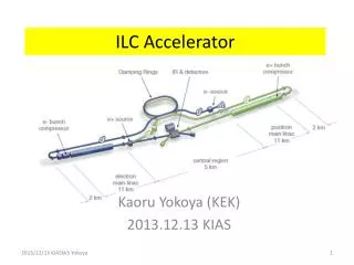
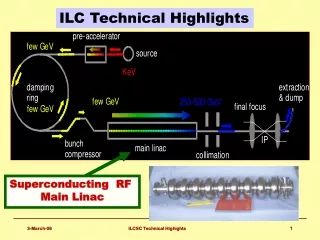
ILC Accelerator Technical Issues Nick Walker LCWS 2005 Stanford University 18.3.2005
Already have two ILC Possibilities TESLA TDR500 GeV (800 GeV) 33km 47 km US Options Study500 GeV (1 TeV)
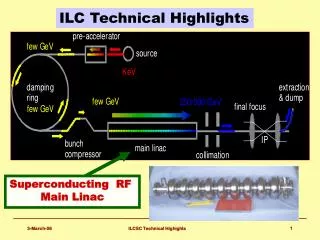
ILC Design Issues After ITRP decision: Back to Basics! Energy Reach ILC Parameters Luminosity
TESLA TDR Parameters peak luminosity 31034 • 31034 cm-2s-1 peak achievable • Possible due to very high beam-beam disruption (Dy) • Well into kink-instability regime (unstable) • Little head room to play with parameterspace
TESLA TDR Parameters peak luminosity 31034 parameterspace
ILC Parameters peak luminosity • Define baseline at relaxed goal of21034 cm-2s-1 • consistent with WWS 500fb-1 in first 4 years • Now have several possible parameter sets (parameter ‘plane’) • Operational flexibility • Sub-system experts to evaluate trade-offs between relevant parameters 21034 parameterspace
ILC Parameters Suggested ILC Beam Parameter Range by Tor Raubenheimer (SLAC) available from: http://www-project.slac.stanford.edu/ilc/ http://ilc.desy.de http://… parameters discussion forum: http://www-project.slac.stanford.edu/ilc/discussion/Default.htm This document intended to provoke your feedback and comment!
Parameter Plane Range of parameters design to achieve 21034
Towards the ILC Baseline Design Decisions to be Made!
Main Linac: The Cost Driver • Biggest single cost item • 10 years of R&D by the TESLA Collaboration has produced a mature technology • But still lots to do…
Main Linac: The Cost Driver • Primary focus of future R&D should be • successful tech. transfer to industry • cost reduction through industrialisation • need extensive effort to achieve high reliability !!! • Euro XFEL project is already doing much of this within Europe • Asia and US should follow • One important question: “What should the design gradient be?”
Gradient versus Length • Higher gradient gives shorter linac • cheaper tunnel / civil engineering • less cavities • (but still need same # klystrons) • Higher gradient needs more refrigeration • ‘cryo-power’ per unit length scales as G2/Q0 • cost of cryoplants goes up!
Simple Cost Scaling general consensus that 35MV/m is close to optimum However Japanese are still pushing for 40-45MV/m 30 MV/m would give safety margin Relative Cost C. Adolphsen (SLAC) Gradient MV/m
Gradient Results from KEK-DESY collaboration must reduce spread (need more statistics) single-cell measurements (in nine-cell cavities) Electropolishing the way to (reproducible) high gradients
TESLA Cavity Design ~1m 9-cell 1.3GHz Niobium Cavity Reference design: has not been modified in 10 years
Possible MinorEnhancement Low Loss Design Small modification to cavity shape reduces peak B field. Increase operation margin. Increases peak E field (field emission) Mechanical stability ??(Lorentz force detuning) KEK currently producing prototypes
More Radical Possibilities Re-entrant 28 cell Super-structure More radical concepts potentially offer greater benefits. But requires major new infrastructure to develop. single-cell achieved45.7 MV/m Q0 ~1010 (Cornell)
Cryomodule Variants TTF ILC # cavities 8 12?spacing 3l/2 l/2?quad loc. end centre? TESLA CM already 3rd generation Main emphasis is on- industrialisation - reliability- cost optimisation EURO XFEL
Cavity Auxiliaries INFN blade tuner TTF TYPE-IIIHP Coupler SACLAY tuner (type III) industrialisation – cost – reliability
Example: Klystron Development THALUS CPI TOSHIBA 10MW 1.4ms Multibeam Klystrons ~650 for 500 GeV +650 for 1 TeV upgrade Other ideas being considered (e.g. sheet beam klystrons)
Global SCRF Test Facilities • TESLA Test Facility (TTF)currently unique in the worldVUV-FEL user facilitytest-bed for both XFEL & ILC • US proposed SMTFCornell, JLab, ANL, FNAL, LBNL, LANL, MIT,MSU, SNS, UPenn, NIU, BNL, SLACcurrently requesting fundingTF for ILC, Proton Driver (and more) • STF @ KEKaggressive schedule to produce high-gradient(~45MV/m) cavities / cryomodules All facilities will be discussed at TESLA CollaborationMeeting 30/3-1/4 at DESY Others (UK proposals?)
Towards the ILC Baseline Design Not cost drivers But can be L performance bottlenecks Many challenges! More Decisions to be Made!
Damping Rings higher Iav smaller circumference (faster kicker) bunch train compression 300km 20km
see A. Wolski’s talk: http://lcdev.kek.jp/ILCWS/Talks/14wg3-10-WG3-10_DR_Wolski.pdf
see A. Wolski’s talk: http://lcdev.kek.jp/ILCWS/Talks/14wg3-10-WG3-10_DR_Wolski.pdf
see A. Wolski’s talk: http://lcdev.kek.jp/ILCWS/Talks/14wg3-10-WG3-10_DR_Wolski.pdf
ATF @ KEK E 1.28 GeV N 21010 e/bunch bunches 1-20 e x/y 1.5nm / 4pm 20 weeks/year 2 weeks/month • emittance tuning • wiggler dynamics • collective effects • multi-bunch • fast kicker technology • diagnostics test bed wiggler magnets
BDS Issues very active (international) group!
BDS Strawman Model • Discussion on angles between the Linacs: • Multi-TeV upgradeability argument is favoured by many • Small crossing angle is disfavoured by some
ATF-2: FFTB @ ATF International Collaboration (ongoing discussions) Begin construction 8.2006 Begin operation 1.2007 • Test of local correction FF optics • 35nm IP beam size • Test facility for stabilisation techniques (beam-based feedback and mechanical: goal 2nm at IP) • Long term stability studies • …
Positron Source • Large amount of charge to produce • Three concepts: • undulator-based (TESLA TDR baseline) • ‘conventional’ • laser Compton based Hotly debated subject.
Undulator-Based 6D e+ emittance small enough that (probably) no pre-DR needed [shifts emphasis/challenge to DR acceptance] Lower n production rates (radiation damage) Need high-energy e- to make e+ (coupled operation) Makes commissioning more difficult Polarised positrons (almost) for free
Conventional • Extrapolation of existing methods • SLC e+ source • Extremely challenging for ILC pulse structure • feasibility still a question • Requires thick target(s) • High(er) n production – radiation damage a primary issue • Large e+ emittance probably means pre-DR needed. • Completely de-couples e+ from e- machine • greater flexibility • operability • commissioning
Reliability / Operability A major issue for ILC – needs much more workCurrent state-of-the-art is Tom Himel study for USCWO
L performance bottleneck Summary • The ILC is ambitious project which pushed the envelope in every subsystem: • Main SCRF linac • sources • damping rings • beam delivery cost driver $$$
Summary • The ILC is ambitious project which pushed the envelope in every subsystem: • Main SCRF linac • sources • damping rings • beam delivery • Still many accelerator physics issues to deal with, but reliability and cost issues are probably the greater challenges • Probably in excess of 3000 man-years already invested in design work. • but still plenty for you to do if you want to join us cost driver $$$ L performance bottleneck