Download
1 / 26
260 likes | 391 Views
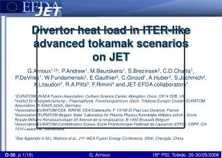
In/Out balance and time scales of ELM divertor heat load in JET and ASDEX Upgrade. T.Eich 1 , A.Kallenbach 1 , W.Fundamenski 2 , A.Herrmann 1 , R.A. Pitts 3 , J.C.Fuchs 1 , S.Devaux 1 , V.Naulin 4 , ASDEX Upgrade Team and JET-EFDA contributors

E N D
In/Out balance and time scales of ELM divertor heat load in JET and ASDEX Upgrade T.Eich1, A.Kallenbach1, W.Fundamenski2, A.Herrmann1 , R.A. Pitts3,J.C.Fuchs1, S.Devaux1, V.Naulin4, ASDEX Upgrade Team and JET-EFDA contributors 1Max-Planck-Institut für Plasmaphysik, 85748 Garching, Germany 2 EURATOM-UKAEA Fusion Association, Abingdon, Oxon, United Kingdom 3 Association Euratom, CRPP-EPFL, 1015 Lausanne, Switzerland 4 Euratom-Association, Risoe-DTU, DK 4000 Roskilde, Denmark 28/05/2008, PSI-2008, Toledo, Spain
Outline of the talk & data base Data base: • Type-I ELMy H-Mode plasma discharges with deuterium • ASDEX Upgrade upper single null discharges (+Ip/-Bt, +Ip/+Bt) • JET lower single null discharges (+Ip/-Bt) optimised for IR studies • All data are ELM averaged (~ 20) and thus filament averaged (~200) Outline of the talk: • A simplified picture for ELM energy transport • Comparison to the empirical scalings for ELM power load time scales • A possible contribution to the observed in/out ELM energy asymmetry • Some preliminary results of the new JET divertor IR camera
Motivation Though good progress for understanding ELM SOL transport is reported, we still do not understand ELM in/out asymmetries Negative Btor • Between ELMs most of the SOL power is deposited on the outer divertor target • During ELMs the power load on the inner target is larger Positive Btor
Note: va= 0 -> Ein/Eout = Nin/Nout =1 A free streaming particle approach (FSP) Working model: All particles during ELMs are released on a time scale, τELM, at the outer midplane and are free streaming along field lines to the inner and outer divertor target (W.Fundamenski et al., PPCF48, p.109 (2006)) outer inner fv v/cs
Comparison of FSP with IR data Field reversed (-B,+I): Ei/Eo = 0.6 Field normal (+B,+I): Ei/Eo = 1.4 Inner Outer far SOL • ELM target energies Ein,out and τin,out enter as fitting parameters • In/out ELM energy asymmetry changes with field, time scales stay similar
Comparison to JET heat fluxes • Same exercise for JET ELM power load for inner and outer target • For outer target power load the agreement appears reasonable • For the inner divertor we use a best guess (due to reduced data quality) Similar time scales in JET compared to AUG due to higher pedestal temperature and longer connection lengths
Comparison to scaling: τIR • For open divertor geometries we find a clear correlation • For closed divertor geometries systematically larger τIR are found • The upper limit concerning material limits is given by the scaling since τIR is shortest then Scaling suggests fast rise of instability ≤ 200us
Comparison to scaling: E(τIR) ptarget 18% JET - outer target time tIR • Within FSP approximation the E(τIR) is 18% of ELM target energy • The temperature peaks slightly later ~50-100us (IR resolution) • The E(τIR) for peak temperature is around 23-27%
Consider a net particle velocity (va≠ 0) Introducing a va = vshift = 0.1cs causes the in/out target energy & particle deposition to be asymmetric with values of Ein/Eout ~ 1.4 and Nin/Nout ~ 1.25 in the limit of fully free streaming particles inner outer fv • Conjecture: vshift arises from pedestal rotation and ExB drifts • Changing the Btor direction inverses the field line pitch at outer midplane
Typical Ein/Eout values as seen experimentally Change of ELM heat fluxes with vshift Same data as slide 5, #16725, normal field Ein+Eout Ein & Eout • Instead of fitting Ein and Eout, the values for Ein+Eout and vshift = 0.1*cs is set • The small delay between inner and outer target contains information about the instability process
New Divertor IR-Camera For JET CFC W IR-Picture when installed
Small & fast window gives 26.3kHz or 38us ELM structure at JET Footprints of single filaments Snapshot of IR camera Spatial resolution is 1.7mm
ELM structure evolution (camera data) 190us 76us before 0us 38us 380us 570us 760us 950us Note, this all happens in less than 1ms
Summary • Parallel time scales of type-I ELMs are described reasonably well for the limit of low collisionality with assumption of free streaming particles • The FSP approach gives a conservative limit for critical power loads • Introducing a shift in the Maxwellian distribution for the particle velocities can reproduce ELM target energy in/out asymmetry • Values to explain ELM energy asymmetries of ~1-2.5 are vshift/cs= 0 - 0.25 • Small observed delay of peak power load between and inner and outer target contains information about ELM instability which we need to understand
Positive Btor Negative Btor Vshift > 0 Vshift < 0 Comparison of ELM target energy and charge T.Eich, JNM 363-365, p. 989, (2007) • The effect of vshift must be working differently for ions and electrons • Comparison of LP and IR (●) reveals energy asymmetry is due to ions • More detailed studies should be adressed with PIC modelling (next talk) For comparison of LP/IR see A.Kallenbach, submitted to Nuclear Fusion (2008)
ELM time + parallel transport • Energy source function • FSP for Linner/cs • FSP for Louter/cs • Inner target power load • Outer target power load
Variation of energy source function Additionally to the FSP approach, we can numerically assume finite numbers for the ELM energy efflux duration and poloidal extension Result: Only very little change in the resulting target heat fluxes which are beyond the diagnostic resolution Which implies : From target fluxes no detailed conclusion on the poloidal extend nor ELM energy release time can be drawn Shown: τELM,release = +/-75us, pol. FWHM = 13m (outer midplane)
JET target power load in ELMy H-Mode • Between ELM most of the SOL power is deposited on the outer divertor target • During ELMs the power load on the inner target is larger (1.5:1) • Example here from the JET MKII-Gas Box divertor and IR optimised Type-I ELMy H-Mode discharges
Filament motion and velocities differ • ELM filaments are observed to decelerate toroidally (e.g. talk by A.Kirk) • Note that velocity components of particles and filament structures are different • Parallel particle velocity in filament does not result in filament rotation • Filament toroidal rotation solely due to perpendicular drifts, dominated by radial electric field • In/Out asymmetry due to field line pitch and pedestal top toroidal rotation direction Inner divertor Inner divertor HFS HFS poloidal angle LFS LFS Normal (+B,+I) Reversed (-B,+I) Outer divertor Outer divertor Toroidal angle
Filament motion and velocities Net velocities Blue:Particles Green : Filament Note: Parallel expansion of filament usually unobservable Toroidal motion of filament ONLY due to V_perp. HFS V_perp V_par V_pol poloidal angle V_tor LFS Normal (+B,+I) Toroidal angle V.Naulin
‘normal’ ion B x grad(B) direction AUG upper divertor • More energy (power) deposited on inner target than on outer target • Charge (current) → net positive charge on inner target • Charge (current) for inner and outer target are equal in absolute size and opposite in sign
‘reversed’ ion B x grad(B) direction AUG upper divertor • More energy (power) deposited on outer target than on inner • Charge (current) → net positive charge on outer target Observation: target with net positive charge receives more energy
ELM energy difference vs. charge difference • The difference of ELM energy on inner and outer target is well correlated with charge difference • Both quantities switch sign with field direction • Situation is not symmetric but line passes through zero line goes through zero Charge (As) for ‘normal’ field Diagnostical artefacts (i.e. surface layer) are neglegible
Comparison JET and ASDEX Upgrade JET AUG Focusing on ‘normal’ field: • JET & AUG + (ELM target energy < 100kJ) : 1 ≤Einner / Eouter≤ 2 • Only JET + (ELM target energy > 100kJ) : Einner / Eouter≈2
Adjust Lo and Li Vshift=0.1*cs