Download
1 / 19
190 likes | 325 Views
Deuterium Inventory in ASDEX Upgrade M. Mayer 1 , V. Rohde 1 , G. Ramos 2 , E. Vainonen-Ahlgren 3 , J. Likonen 3 , A. Herrmann 1 , and ASDEX Upgrade Team 1 Max-Planck-Institut für Plasmaphysik, EURATOM Association, Garching, Germany

E N D
Deuterium Inventory in ASDEX Upgrade M. Mayer1, V. Rohde1, G. Ramos2, E. Vainonen-Ahlgren3, J. Likonen3, A. Herrmann1, and ASDEX Upgrade Team 1 Max-Planck-Institut für Plasmaphysik, EURATOM Association, Garching, Germany 2 CICATA-Qro, Instituto Politécnico Nacional, Querétaro, México 3 Association EURATOM-TEKES, VTT Processes, Espoo, Finland • Deuterium inventory – Inner, outer divertor – Gaps between tiles – Remote areas – Upper divertor, limiter, …
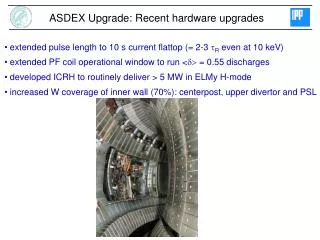
Wall areas and analysis methods upper divertor • Analysis methods • NRA D(3He,p)a - 1000 keV: D inventory in 2 µm - 2500 keV: D inventory in 10 µm • Marker stripes for RBS - Deposition of B, C (talk on 9.5.2007) • SIMS • Data for 2002-2003 and 2004-2005 • campaigns • Carbon dominated machine upper PSL inner heat shield ICRH limiter lower PSL inner divertor pump duct outer divertor roof baffle
6A 3B 3A 6B 5 2 4 9B 1B 1A 10 9C 9A Divertor 2002–2003 Inner divertor - Deposition on all tiles Roof baffle - Deposition directly opposite of inner strike point - Otherwise small D inventories Outer divertor - Erosion area, small D inventories - Localized deposition in divertor corner
Inner divertor 2002–2003 and 2004–2005 2004–2005, 3060 s 2002–2003, 4860 s • D/(B+C) = 0.4 is upper limit (and often typical) for inner divertor tiles • Observed D/(B+C) may be lower, B+C more robust indicator for D inventory
Inner divertor gaps 2004–2005 • Exponential decay with l = 1–2 mm (plasma-exposed) and l = 20–30 mm • Inventory predominantly on plasma-hit areas
6B 5 Inner divertor gaps 2004–2005 (2) D-inventory Tile in gap without gap [µg] [µg] 6B 130 200 5 770 940 Identical inventory with and without gap Inner divertor gaps do not increase inventory, but change spatial distribution As expected for high-sticking particles
3B 3A 2 1B 1A 10 Outer divertor 2002–2003 and 2004–2005 2004–2005 2002–2003 • Net erosion in most of outer divertor, resulting in small inventories • Small deposition area in lower divertor corner • Material probably originates from outer strike point • Inventory can be minimised by strike-point sweeps
Outer divertor gaps 2004–2005 • Exponential decay with l = 20–30 mm • Inventory very small, no difference between plasma-hit and plasma-shadowed side
Below roof baffle 2002–2003 • Maximum inventories in line-of-sight to strike points • Small inventories at shadowed areas • Layer deposition by particles with high (~ 1) sticking probability
Pump duct 2000–2001 • Very small inventory in 2000–2001 • Also very small in 2001–2002, maximum 5×10¹⁵ D-atoms • Flange from pump duct 1996-2006: 2×10¹⁵ D-atoms • Negligible inventory in pump ducts • Low sticking species reach pump duct, but have only very small contribution to D inventory
a1 I1 ? 86I PSL Upper divertor 2003–2004 • Small inventory, compared to lower divertor • Inventory mostly due to boronizations • Erosion at strike points, deposition towards inner and outer side
ICRH limiter B 1 4 8 Auxiliary limiter 2005–2006 • Complex distributions • Low amount of D, small area • Small inventory
Deuterium retention in 2002–2003 Retention Fuelling from (B+C), assuming D/(B+C)=0.4 Long-term D retention 3–4% of fuelling Majority on divertor tiles (50-60%), followed by remote areas (20%) Gas balance (Mertens 2003): 10–20%Marginal agreement, taking error bars into account
Outer divertor gaps 2004–2005 • Exponential decay with l = 20–30 mm • Inventory very small, no difference between plasma-hit and plasma-shadowed side
Outer divertor gaps (2) • Max D inventory after 2004–2005 campaign: 6×10¹⁷ D-atoms in 1000 discharges • Castellated W (Krieger 2006): 3×10¹⁷ D-atoms in 3 discharges • Difference by 2 orders of magnitude • – Exposure of castellated W in C environment, and tile 2 in W environment?– Re-erosion by atomic H, nonlinear growth? Krieger 2006
Predictions for ITER ITER fuelling: 50 g T 2 g D-retention for 4% retention fraction Net deposition and net erosion areas predicted at inner and outer ITER target Not observed in today’s machines (different plasma parameters) ITER predictions are based oncalculations which are not wellbenchmarked AUG offers unique data base A. Kirschner 2006
W coverage in AUG 2002 – 2006 Step by step replacement of C offers unique possibility to identifynet carbon sources Neu 2007
2002 - 2003 2003 - 2004 2004 - 2005 2005 - 2006 C-concentration in plasma • Data for ‘standard’ H-mode • Decrease of core C-concentration by factor ~2 • Scatter of data due to • Boronizations • Discharge history • Operational imperfections • … • Data from 2002–2003 and 2004–2005 • Carbon dominated machine Kallenbach 2007