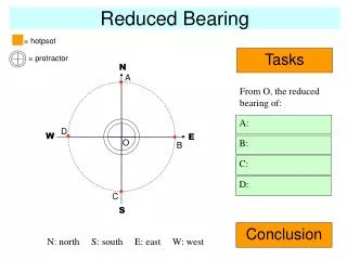
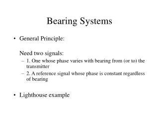
Bearing Systems
Bearing Systems. General Principle: Need two signals: 1. One whose phase varies with bearing from (or to) the transmitter 2. A reference signal whose phase is constant regardless of bearing Lighthouse example. VOR (VHF Omnirange).

Bearing Systems
E N D
Presentation Transcript
Bearing Systems • General Principle: Need two signals: • 1. One whose phase varies with bearing from (or to) the transmitter • 2. A reference signal whose phase is constant regardless of bearing • Lighthouse example
VOR (VHF Omnirange) • Frequency: 108-112MHz (even tenths) 112-118MHz (every 0.1 MHz) • RF Power Level Output (Ground Station): 100W
VOR • In VOR, the variable signal is provided by a limacon antenna pattern which rotates clockwise at 30Hz. Note: a limacon has the equation Thus an observer at any point measures an RF signal , amplitude modulated at 30 Hz
VOR VOR ANTENNA PATTERN
VOR REFERENCE SIGNAL The Reference Signal is radiated in an omnidirectional pattern. It is amplitude modulated by a 9960Hz subcarrier. This, in turn, is frequency modulated at 30Hz The FM (reference) modulation is in phase with the variable pattern when the observer is North of the station (can be referenced to Magnetic or True)
VOR SIGNAL GENERATION Note the 1020Hz identifier
ANTENNA ARRAYS • It is often impossible to generate a desired antenna pattern with just one antenna • Using two or more antenna elements provides the designer with more design variables e.g. • Number of elements • Physical arrangement of elements • Amplitude and Phase of input signals
ANTENNA ARRAYS Two Element Example • l/2 Antenna Pattern Transmitter
ANTENNA ARRAYS Two Element Example • l/2 Antenna Pattern 90deg Transmitter
VOR RECEIVER HSI (HORIZONTAL SITUATION INDICATOR)
VOR ERRORS • Since the system depends on the antenna pattern, any distortion of the pattern will cause errors • Internal sources of error: • antenna or feed mismatch • External sources of error: • Reflections from buildings, terrain, trees, etc
DOPPLER VOR • Sometimes a particular site has too many reflecting objects to permit the operation of a standard VOR • In this case, a Doppler VOR is installed. • This permits a large aperture antenna array to be used,i.e. an antenna array covering a large area. • A large antenna array uses space diversity
DOPPLER VOR EFFECT OF APERTURE
DOPPLER VOR If an antenna, radiating a signal at a carrier frequency fC , is placed on the edge of a platform which rotates at an angular rate w, a receiver at a distance will observe that the carrier is frequency modulated at the angular frequency w. This is due to the Doppler shift caused by the relative motion of the antenna and receiver .
fc r w DOPPLER VOR v=wr fR=fCv/c
fc+9960 • 30Hz fc-9960 DOPPLER VOR Note: To maintain the correct relationship between reference and variable signals, the signal rotation is counterclockwise fc
VOR as a NAVIGATION AID • Accuracy: ± 3º • Availability: (Two transmitters) 99.9% • Integrity: Ground - monitors Air- receiver measures signal strength and modulation depth • Availability: