Download
1 / 46
460 likes | 631 Views
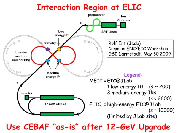
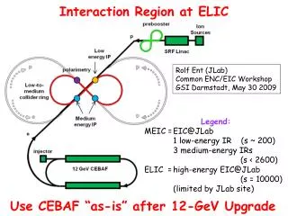
Interaction Region at ELIC. Rolf Ent (JLab) Common ENC/EIC Workshop GSI Darmstadt, May 30 2009. Legend: MEIC = EIC@JLab 1 low-energy IR (s ~ 200) 3 medium-energy IRs (s < 2600) ELIC = high-energy EIC@JLab (s = 10000) (limited by JLab site).

E N D
Interaction Region at ELIC Rolf Ent (JLab) Common ENC/EIC Workshop GSI Darmstadt, May 30 2009 Legend: MEIC = EIC@JLab 1 low-energy IR (s ~ 200) 3 medium-energy IRs (s < 2600) ELIC = high-energy EIC@JLab (s = 10000) (limited by JLab site) Use CEBAF “as-is” after 12-GeV Upgrade
EIC@JLab High-Level Overview • Hadrons in QCD are relativistic many-body systems, with a fluctuating number of elementary quark/gluon constituents and a very rich structure of the wave function. • With 12 GeV we study mostly the valence quark component, which can be described with methods of nuclear physics (fixed number of particles). • With an (M)EIC we enter the region where the many-body nature of hadrons, coupling to vacuum excitations, etc., become manifest and the theoretical methods are those of quantum field theory.
EIC@JLab High-Level Summary What science goals are accessed/appropriate? • Gluon and sea quark (transverse) imaging of the nucleon • Nucleon Spin (DG vs. ln(Q2), transverse momentum) • Nuclei in QCD (gluons in nuclei, quark/gluon energy loss) • QCD Vacuum and Hadron Structure and Creation • Energies and figure-8 ring shape and size chosen to optimize • polarization and luminosity • Try to minimize headaches due to synchrotron and large leaps in • state-of-the-art through R&D • 4 Interaction Regions, with function and size optimized to “decouple” • detector from accelerator – can optimize later to increase luminosity
(M)EIC@JLab: Basic Considerations • Optimize for nucleon/nuclear structure in QCD • - access to sea quarks/gluons (x > 0.01 or so) • - deep exclusive scattering at Q2 > 10 • - any QCD machine needs range in Q2 • s = 1000 or so to reach decade in Q2 • high luminosity, >1034 and approaching 1035, essential • lower, more symmetric energies for resolution & PID • Not driven by gluon saturation (small-x physics) … • “Sweet spot” for • - electron energies from 3 to 5 GeV (minimize synchrotron) • proton energies ranging from 30 to 60 GeV • but larger range of s accessible (Ee = 11 GeV, Ep = 12 GeV) • Decrease R&D needs, while maintaining high luminosities • Potential future upgrade to high-energy collider, • but no compromising of nucleon structure capabilities
MEIC/ELIC Figure-8 Collider Ring Footprint Medium Energy IP Low Energy IP Snake Insertion 60° • MEIC luminosity is limited by • Synchrotron radiation power of e-beam • requires large ring (arc) length • Space charge effect of p-beam • requires small ring length • Multiple IRs require long straight • sections. Recent thinking: start with • 18 meter detector space for all IRs • to make life easier (?) • Straight sections also hold other required components (electron cooling, injection & ejections, etc.)
y z Figure-8 (half) Straight Sections & Interaction Regions Straight section spin rotator spin rotator vertical bend vertical bend e e collision point collision point arc bend arc dipoles ~0.4 m i i ~0.4 m Vertical crossing angle (~24 mrad) Ion beam spin rotators vertical bend vertical bend 1st (!) detector IR Minimizing crossing angle reduces crab cavity challenges & required R&D Changed to +/- 9 meters Interaction Region ~ 60 m IP FODO Chrom Chrom FODO FF FF Matching quads Matching quad Crab cavity Crab cavity Detector space b chrom.
Asymmetric IR with large ‘magnet free’ region IR (9m + 9m) emittance asymmetry - ‘flat beams’, ex/ey ~ 10 final focus asymmetry (b*), bx/by ~ 5 (Alex Bogacz) • Manageable beam sizes at the FF quads (sRMS ~ 5 mm) • The longest distance between the IP and the first quad is critical for FF quad apertures • Initial focusing of larger emittance plane results in minimized beam sizes in both planes • IR design consistent with the luminosity of 1034
(Longitudinal) Asymmetric IR - Findings • Longitudinally asymmetric IR has no advantage • The longest distance between the IP and the first quad is critical for FF quad apertures • (9m + 3m) IR as challenging as (9m + 9m) IR • Triplet vs Doublet FF Optics • Same magnet apertures required • Triplet focusing more compact • Doublet focusing more suitable for ‘interleaved’ FFs for smaller beam crossing • Flat beams favorable, ex/ey ~ 10 • Beam-beam interaction • Luminosity optimization • Asymmetric focusing (b*) for flat beams desirable, bx/by ~ 5 • Initial focusing of larger emittance plane results in minimized beam sizes in both planes • Manageable beam sizes on FF quads, sRMS ~ 5mm
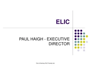
IR Magnet Layout If ELIC w. 8 m IR space Proton FF quads of 1.8 (3.0) m with 20.8 (12.0) kG/cm Cross section of quad with beam passing through Magnetic field in cold yoke around electron pass (Paul Brindza) Proton FF quads 9 m Vertical crossing angle No need for such Lambertson-type quads with MEIC (18 m IR space) IP Electron FF quads
Crab Crossing • High repetition rate requires crab crossing to avoid parasitic beam-beam interaction • Crab cavities needed to restore head-on collision & avoid luminosity reduction • Minimizing crossing angle reduces crab cavity challenges & required R&D SymmetryBreaking(05/11/09) “Record luminosity collisions due to “crab” crossing, • State-of-art: • KEKB Squashed cell@TM110 Mode • Crossing angle • = 2 x 11 mrad • Vkick=1.4 MV • Esp= 21 MV/m
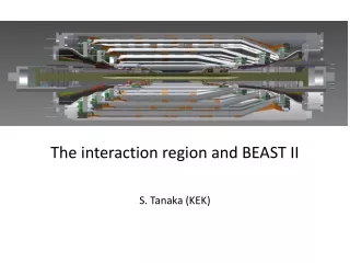
MEIC R&D: Crab Crossing • Crab cavity development (~24 mrad crossing angle for 5 GeV electrons and 60 GeV ions, 18 meter IR space) • Electron: 1 MV – within state of art (KEK) • Ion: 5 MV (Integrated B field on axis 38G/4m) Crab Crossing R&D program • Understand gradient limit and packing factor • Multi-cell SRF crab cavity design capable for high current operation. • Phase and amplitude stability requirements • Beam dynamics study with crab crossing Single cell Multi cell (top) Multi-cell TM110 and Loaded Structure of Crabbing Cavity (JLab/Cockcroft/Lancaster) (left) Compact TEM-type, parallel-bar Single cell: 37x50cm, 4MV@500 MHz Multi cell: nx37 cm, nx4MV J. Delayen, H. Wang, PRST 2009 J. Delayen, JLab seminar, 02/19/09
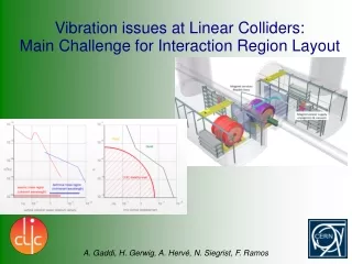
Synchroton Power/Backgrounds • Synchrotron radiation in IR : lower electron energy than HERA! • Synchrotron Power ~ I E4 / R • ELIC / HERA II current ratio: ~ 0.55 A / 45 mA = 12 • Electron energy ratio: (10 GeV/ 27.5 GeV)4 = 0.017 • ELIC / HERA radius: (0.18/1.0) = 0.18 1/R = 5.6 • Use of crab crossing makes this simpler for IR: • Confirmed for (old) ELIC 100 mr crab crossing case } Same! Alex Bogacz, Slava Derbenev, Lia Merminga (JLab) and Christoph Montag (BNL)
Synchroton Power/Backgrounds • Synchrotron radiation in IR : simplified as electron energy low! • Synchrotron Power ~ I E4 / R • EIC@JLab / HERA II current ratio: 2000 mA / 45 mA = 44 • Electron energy ratio: (5 GeV / 27.5 GeV)4 = 0.001 • Same power if bending radius at detector is 20 times smaller • Use of (24 mr) crab crossing makes this even simpler • Such simplification was earlier confirmed for an (old) ELIC 10 GeV electron beam energy and 100 mr crab crossing angle case (where synchrotron power estimate is similar to HERA) Again Detailed IR design needed, but no obvious problems @ 5 GeV
EIC@JLab – IR Assumptions Can one use pluses of green field MEIC in IR design? - Four Interaction Regions available - novel design ideas promise high luminosity - more symmetric beam energies “central” angles - figure-8 design optimized for spin (no impact on IR design) Main IR assumptions: - concentrate on one IR as main-purpose detector - separate diffractive/low-Q2 “Caldwell-type” detector from this main-purpose detector - define relatively long (18 meter) fixed detector space (albeit with loss in luminosity – this 18 meter space is what Yuhong used in his presentation on MEIC/ELIC design) - use flexibility in RF frequency to advantage (high RF for main detector physics?, low for eA etc.)
EIC@JLab IR Assumptions Medium Energy IP Snake Insertion 60° Low Energy IP IR1: General Purpose detector (but not diffractive/low-Q2) IR3: Diffractive/Low-Q2 detector p e IR4: Low Energy detector IR2: Polarimetry etc. Low Energy: 12 on 3-5 [sqrt(s) only factor of three higher than 12-GeV program] Medium Energy: 30-60 on 3-5 (11) IR Regions: +/- 9 meter
1H(e,e’π+)n – Kinematics MEIC@JLab 11 on 60 GeV2 MEIC@JLab 4 on 60 GeV2 MEIC@JLab 4 on 12 GeV2 ~ ENC@GSI Staged eRHIC 4 on 250 GeV2 Staged eRHIC 2 on 250 GeV2
1H(e,e’π+)n – Electron Kinematics – Q2 (Tanja Horn) No need for very low Qe, or at least not with very good energy resolution.
1H(e,e’π+)n – Pion Kinematics – P (Tanja Horn) Lower proton energies better to map cones around hadrons for deep exclusive and SIDIS
1H(e,e’π+)n – Electron Kinematics – P (Tanja Horn) More symmetric and lower energies are better for energy resolution
1H(e,e’π+)n – Pion Kinematics – Q2 (Tanja Horn) No need to push to most forward hadron angles for reasonable Q2 in DES + SIDIS
1H(e,e’π+)n – Neutron Kinematics – t Want 0 < t < 1 GeV! DQ = 1.3 DQ = 1.3 DQ = 5 (Tanja Horn) DQ = 0.3 DQ = 0.3 dt/t ~ t/Ep lower Ep better
1H(e,e’π+)n – Scattered Neutron, 4 on 60 • Low –t neutrons (or protons) are emitted at very small angles with respect to the beam line, outside the main detector acceptance • Between 0.2 and 1.5 degrees, or 3 and 25 mrad • If first IR magnet element 9 m away 2.7 to 22.5 cm • Better to assume all detection before 1st IR magnet? • A separate detector placed tangent to the proton beam line away from the intersection region is required – not clear how to do yet
General Considerations for Magnetic Fields • Solenoid is “easy” field, but not much field at small scattering angles • Toroid would give better field at small angles but with an asymmetric acceptance • Improves acceptance for positive hadrons (outbending) • Improves detection of high Q2 electrons (inbending) • Limits acceptance at very small angles (~3o?) due to coils • (want 1o or so: resolved with $$ barrel toroid? Other tricks? • May limit acceptance for π+π- detection • Vary Solenoid field to see how far one can push • and compare with toroidal field • But … also need runs with lower central solenoid field to access low-momentum reaction products from e.g. open charm production (~0.5 GeV/c) • Could also add central toroidal or dipole field(s) to solenoid • Small dipole component may be useful for lattice design (~0.3-0.5 Tm?) • goal of dipole field on electron side to optimize resolutions • goal of dipole field on hadron side to “peel” charged particles • away from beam
Formulas – used in parametric MC (Tanja Horn, Richard Milner, Rolf Ent) Multiple scattering contribution: Intrinsic contribution (first term): • z = charge of particle • L = total track length through detector (m) • γ= angle of incidence w.r.t. normal of detector plane • nr.l. = number of radiation lengths in detector msc • B=central field (T) • σrφ=position resolution (m) • L’=length of transverse path through field (m) • N=number of measurements intr • Assumptions: • circular detectors around interaction point • nr.l. = 0.03 (from Hall D CDC) • simulations only done for pions (for now)
Solenoid Fields - Overview Conclusion: ~4-5 Tesla fields, with length scale ~ inner diameter scale o.k. Simulations showed we would need some 5-10 (?) Tm on central ion side, AND some additional 2 Tm magnetic field in the ion (< 20 deg?) direction to improve resolutions. Field needs are not too far off from CLAS12! ID ~ length solenoid likely scenario is some 3-4 meter long and 3-4 m ID
Solenoid and dipole field p = 50 GeV p = 5 GeV As expected, substantially improves resolutions at small angles
Solenoid and CLAS12 toroidal field (add dipole) (add toroid) p = 50 GeV p = 50 GeV Does the same trick, but would get acceptance loss at small angles (~3o?) Not likely to push this to 1o, but we are still looking at it.
Solenoid and CLAS12 toroidal field (add toroid) (add toroid, zoom) p = 50 GeV p = 50 GeV >1% for angles <2deg Initial solenoid: B=4T, L=5m, D=2.5m
Dipole field requirement on hadron side • 0.5-1 Tm dipole component, or 2 Tm separate dipole sufficient on hadron side to peel the charged particles away from beam line and allow for tagging/vetoing? • Need to fold in map of angle vs. momentum of particles of interest to better constrain. • Of course, such options also need to be checked for resolutions required for SIDIS and DES reactions. Deflection @ 5 meters
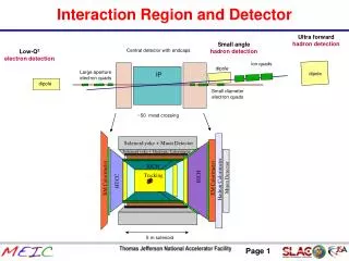
ELIC detector cartoon - ~May. 09 8 meters (for scale) 140 degrees Offset IP ID ~ length solenoid TOF HCAL ECAL Tracking DIRC dipole HTCC RICH Add’l dipole field needed on ion side! solenoid No need for add’l dipole if non-diffractive, non-low-Q2 detector: Q > 10o But, 9 m space exists add dipole, HCAL? e beam Ion beam
Benefit from data transport LEP [CLAS12 DAQ/Fast electronics will be able to meet event rates of up to 10,000 kHz, 100 MB/s data rates, at <15% dead time]
CLAS12 Trigger System • Level1 Trigger Latency ~ 3 μs • Level2 Trigger Latency ~ 7 us Front-End Crate Trigger Distribution Crate VXS Crate VXS Crate (19 crates) Detector Signals TD TS TS Fiber Optic Links Clock/Trigger (16bits @ 62.5MHz (12) (up to 16) (1) (1) (1) (1) (1) VXS Crate Fiber Optic Link (~100 m) (64bits @ 125 MHz) SSP GTP RFP fADC250 (6) (1) (6) CTP Crate Trigger Processor Copper Ribbon Cable (~1.5 m) (32bits @ 250 MHz) (1) Global Trigger Crate SD Signal Distribution TI Trigger Interface Not a synchronized trigger! VXS Backplane
Numerical Example at High Luminosity • At a luminosity of 1035 cm-2s-1, the total hadronic production rate is about 1 x 10⁷ s-1 • Assume a data-acquisition capability of 5,000 s-1 • [CLAS @ Moment, at dead times of 15%, has achieved an event rate of up to 8,000 s-1 (10,000 peak), and a data rate of 35 MB/s, using pipeline TDCs, dual-CPU ROCs, and multiprocessing in Event Builder] • Trigger would need to provide a factor of 2,000 rejection of hadronic events: seems challenging but near reality (CLAS12 assumes >2,000). [CLAS12 DAQ/Fast electronics will be able to meet event rates of up to 10,000 kHz, 100 MB/s data rates, at <15% dead time, by using all pipelined electronics, VXS, + increased data transport]
Bunch Spacing from Detector Point of View CLAS operates at a 500 MHz bunch frequency. The e- can be traced back to the specific bunch, which is then used as “RF time tag” to calibrate the detectors for the hadrons. Question: What are the implications in collider mode? 1. For the specific e-ion process, you still have the e- tag 2. Collection times for (fast) detection devices is 10-20 ns (e.g., silicon, scintillator, and PMT’s, but not for e.g. Ar calorimetry) 3. Use a pipelined ultrafast DAQ/electronics system, but NO NEED to synchronize with RF bunch frequency – we don’t do it now either. 4. Digitization allows determination of time less than the resolving time of the specific detector (now, calibration becomes the main issue) 5. The multiplicity w.r.t. CLAS12 only increases by a factor of 2-4, and the luminosity is close to the same hadronic rates not dissimilar. 6. Hence, can one untangle the interactions separated in time by less than the resolving time of the detector in the face of pileup? 7. Yes. If CLAS and CLAS12 can, so can MEIC. (backgrounds expected to be low with proper choice of IR location).
“Proof of Principle” “Easy” at a fixed-target facility with a 500 MHz beam structure 2/3 ns spacing may be too short to “pick bucket”, but that simply means three random peaks are under the coincidence one. Similar as a DC background, RF frequency in principle does not matter. But, the real/random ratio does matter!
Hadronic Background – scaling w. HERA (Pawel Nadel-Turonski) • Hadronic Random Background: • assumed to be governed by ion-residual vacuum gas (mainly H) interactions • s(pp) nearly independent of energy • EIC@JLab background rates comparable to HERA II • Distance between dipoles and detector: 40 m / 120 m = 0.3 • Average hadron multiplicity: ~ (60 GeV / 920 GeV)1/4 = 0.5 • Ion beam current: 0.7 A / 0.1 A = 7 • Vacuum (10-9torr?) easier to maintain in smaller ring • Signal-to-(beam-related) background is 103 times better • EIC@JLab luminosity: ~5 x 1034 cm-2 s-1 • HERA luminosity: ~5 x 1031 cm-2 s-1
Conclusion on IR/detector studies • Great advantage by separating diffractive/low-Q2 “Caldwell-type” detector from main DIS/SIDIS/DES detector! Is this o.k.? • Since luminosity requirements for eA and polarized ep are vastly different, this does not seem a big issue. • Life also simplified by first starting with large detector space and avoiding complicated detector/accelerator interfaces (if we can…). • Lower beam energies (than 250 GeV) make SIDIS and DES experiments simpler (but they are still difficult). For DES, it may be mandatory if one needs to optimize t-resolution. • More symmetric energies is advantageous for good resolutions and easier particle Id. • Need a field beyond a solenoid field to “peel” charged particles off beam for such deep exclusive processes. • Studies ongoing on whether solenoid + dipole, solenoid + barrel or end-cap toroid, or other magnet configurations are optimal. • Initial studies show coherent nuclear processes also accessible by angle measurements after magnetic field (need good dispersion). • Have started thinking how to handle high luminosity from detector/electronics/DAQ point of view. Short straight section before IR is a plus in terms of background.
Recent Progress towards a High-Luminosity EIC at JLab Large effort by the MEIC/ELIC Study Group Nuclear Physics (exp.) Tanja Horn Charles Hyde Franz Klein Pawel Nadel-Turonski (thy) Vadim Guzey Christian Weiss CASA Alex Bogacz Slava Derbenev Geoff Krafft Yuhong Zhang (+ help from many others) With input from Larry Cardman Andrew Hutton Hugh Montgomery Tony Thomas
Multiplicity for High-Energy Hadron Interactions F. Braccella and L. Popova, J. Phys. G 21 (1995) 1379 My Simple Estimate: Total Multiplicity ~ s1/4 s1/2 (GeV) n (article) 2s1/4 20 (ISR/FNAL) 9 9 540 (SPS) 45 46 1800 82 86 (close to empirical observation in CLAS) CLAS (L = 2 x 1034) n = 3.7 CLAS12 (L = 1 x 1035) n = 4.2 EIC Ecm = 12 (MEIC-Low E) 7 51 (MEIC-Hi E) 14 100 (ELIC) 20 Factor of 2-4 }
JLab Crab Cavity Development Multi-cell TM110 and Loaded Structure of Crabbing Cavity (JLab/Cockcroft/Lancaster) Elliptical squashed SRF cavity R&D for APS (JLab/LBNL/AL/Tsinghua Univ.) H. Wang, R. Rimmer, 12/10/2008 Muon Collider Design Workshop Single cell J. Delayen, H. Wang, PRST 2009 J. Delayen, JLab seminar, 02/19/09 • New (Innovative) Program • Compact TEM-type, parallel-bar • Deflecting 12 GeV CEBAF • Crabbing ELIC • Providing high transverse kinking • Single cell: 37x50cm, 4 MV@500MHz • Multi-cell: ~ n x (37 cm), n x (4 MV) E&M Fields Multi cell
Great News From KEK KEK Press Release (05/11/09) “Using Crab Cavities, KEKB Breaks Luminosity World Record” SymmetryBreaking(05/11/09) “Record luminosity collisions due to “crab” crossing, Trick: 28 skew sextupoles
Maximum Synchrotron Radiation Line Density Y. Suetsugu, et.al, PAC2003 • ELIC sets maximum line power density to 10kW/m 18MW total power • MEIC can assume a more aggressive power line density, ~20 kW/m, since this special beam pipe still keeps the total power under 10 MW total power (cost: $2/W), due to the smaller ring size