Download
1 / 25
250 likes | 275 Views
Learn about how vibrations degrade beam luminosity at linear colliders, the sources of vibrations, mitigation strategies including vibration amplification by detectors, and the push-pull technique. Discover the similarities and differences between ILC and CLIC, along with future outlook.

E N D
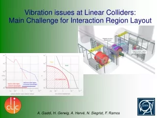
Vibration issues at Linear Colliders: Main Challenge for Interaction Region Layout A. Gaddi, H. Gerwig, A. Hervé, N. Siegrist, F. Ramos
Talk index. 1. How vibration deteriorate beam luminosity 2. ILC vs CLIC: similarity and diversity 3. Vibration sources 4. Vibration mitigation 5. Push-pull & related issues 6. Conclusions & Outlook
How vibrations deteriorate beam luminosity. The high beam luminosity demanded by future linear colliders is achieved by squeezing to nano-metric scale the colliding bunches of particles. This happens in the two final magnets of the accelerator, called also Final Focus quadrupoles. In order to collide beams, FF quads must be aligned to the interaction point at a distance of about 7 meters and kept in position with a precision of the same order of magnitude as the beam size, i.e. about 20nm for ILC and 0.1nm for CLIC (rms displacement at 4Hz). It is important to note that it is their relative stability that counts rather than their absolute stability.
FF quads integration to detector. Final Focus quads are installed very close to the interaction point, that is also the detector centre, making their integration within the detector itself rather difficult.
ILC vs CLIC: similarity and diversity. • ILC: • - Final focus magnets supported by detectors • Large “noise budget” • Stabilize detectors • Avoid noise sources on detectors or nearby • Difficult modelling CLIC: - Final focus magnets supported from accelerator tunnel - Small “noise budget” - Less constraints on detectors - Stabilize small objects - Simpler modelling/prototyping
Vibration sources. Ground seismic motion: 0 < f < 4 Hz – x(f) = 10-8/f2 (m/sqrt(Hz)), for 0.1 < f < 4Hz Human induced noise: 1 < f < 50 Hz
Vibration mitigation (1): detectors amplify vibrations! It has been measured that detectors (if not designed on purpose) amplify the ground motion by more than a factor 10 at frequencies above 1Hz. Measurements done at CMS by EN-MME Group/CERN
Vibration mitigation (2). Isolate ground below final focus magnets. At frequency below few Hz, the ground vibration is the main source of noise. Measurements done at LHC show that ground vibration is about 10 times greater than allowed for CLIC. A passive isolation slab, at the end of the accelerator tunnel, has been proposed to reduce the injected noise at frequency in the range 1 – 50Hz. This device, called pre-isolator, consists in a 50 – 100 tons massive concrete slab, resting on several springs and dampers. It requires a combined design effort from the point of view of the civil engineering and the associated mechanics.
Vibration mitigation (3). Reduce human induced noise. Avoid installing rotating machines nearby the detector or the final focus magnets. This implies, for detectors, long transfer lines for power, fluids (including cryogenics) and data. As detectors move from garage to beam-line every 4 – 6 weeks, transfer lines have to be flexible and run into dedicated cable-chains. Trenches for these large cable-chains have to be included in the civil engineering layout of the experimental cavern.
Vibration mitigation (4). • The final focus magnets stabilization chain. • No single system can stabilize a large and complex object like an accelerator magnet in the frequency range from 0 to 1kHz at the level of nanometers. • At CLIC we have envisaged a chain of systems, each one specific to a given bandwidth and dynamic range: • The pre-alignement acts at lowest frequencies within a range of several millimeters. Its main scope is to compensate for slow ground motions (tidal cycles, ground slab movements due to local geology, deformations due to load transfer(1)…) and thus suppress external noise sources at f <1 Hz. • The main stabilization system is integrated inside the final focus support tube and acts in the medium frequency range and at the micro-metric scale. Its scope is essentially to damp the FF quads internal modes that could be exited by residual external noise. • Finally, the beam-feedback system acts at higher frequencies, directly on the incoming particle beam, deviating its trajectory by a few nanometers. (1) Next slide: Push-pull & related issues
Push-pull & related issues. The exchange of the detector on the beam-line every 4 - 6 weeks, implies flexible transfer lines and an absolute reliability of the platform moving system, on top of which the detector sits. Moving the platform with the associated detector (some 15,000tons overall), could result in a periodic slow settlement of the cavern foundations. The accelerator pre-alignement system need to be designed with enough dynamic range to cope with this, as the other stabilization systems have a much reduced range.
Conclusions & outlook. • Reduce seismic vibration: • CLIC requirements, more severe than ILC, drive design choice such as supporting the FF quads from the accelerator tunnel • Site dependency (deep site, shallow site, ground structure, …) • Civil engineering impact (foundations, coherent wavelength issue, …) • Reduce technical noise: • Smart experimental area layout • Transfer lines for power, fluids, detector data • Final specifications are clearly given at the level of beam-optics, need to translate them into an engineering design: • close collaboration between Civil Engineering, General Services & Detector Engineers.
Tunnel Pre-isolator. Attenuate, at its source, ground motion vertical excitations, in the range 1 – 50 Hz, to make life easier to the following stabilization systems. Objective. • Stabilize FF magnets to better than 0.2 nm (rms) at 4 Hz, • using an integrated approach of three systems, each one • with its dynamic range and frequency response: • Passive pre-isolator • Active mechanical stabilization • Beam-based stabilization
Pre-isolator – How does it work ? + Low dynamic stiffness (k) mount natural frequency around 1 Hz Acts as a low-pass filter for the ground motion (w) Large mass (m) between 50 and 100 tons Provides the inertia necessary to withstand the external disturbances (Fa), such as air flow, acoustic pressure, etc.)
How can it be realized ? QF1 Walk-on-floor QD0 QD0 support tube Mass Elastic support conceptual design
Response to excitation in the vertical direction. 1 Hz 51.2 Hz Good performance above the first resonance peak
Random vibration response. Vertical ground motion at CMS.
Random vibration response. 2.9 nm 0.1 nm Vertical ground motion at CMS. 4 Hz Reduction in r.m.s. displacements by a factor 30 above 4 Hz
Example of pre-isolator application in industry. Vibration isolation system at the Centre for Metrology and Accreditation – Helsinki, Finland 4 independent seismic masses (3x70 ton + 1x140 ton) 0.8 Hz pneumatic vibration isolators (“air springs”)
Experimental set-up – How ? The prototype needs to be: Simple to design/build/assemble Easy to “debug” & tune Cheap Frictionless pivotal joints Center of mass Proposal: 40 ton mass supported by 4 structural beams acting as flexural springs
Experimental set-up – expected performance. Performance in ideal conditions (ground motion only). 1.55 Hz CMS floor @Pre-isolator Transmissibility Displacement P.S.D. 2.9nm at CMS floor 15x 0.2 nm at Pre-isolator Integrated R.M.S. Displacement
Experimental set-up – position of the vibration sensors. Mass Foot Ground Flex beam
Experimental setup – first results:reconstructed center movements. tilt unknown feet resonances