Download

1 / 37
370 likes | 482 Views
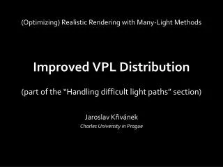
This paper presents advanced methods for optimizing Visible Point Light (VPL) distribution to enhance realistic rendering, particularly in large environments. It discusses challenges of VPL rendering, such as ensuring VPLs are adequately placed where needed and methods for rejecting unimportant VPLs. The approaches include Metropolis sampling and path tracing from the camera to improve efficiency. We also explore local and global light interactions, addressing local inter-reflections to achieve better rendering quality. The findings highlight the importance of distributing VPLs proportionately based on their image contribution.

E N D
Improved VPL Distribution • (Optimizing) Realistic Rendering with Many-Light Methods (part of the “Handling difficult light paths” section) Jaroslav Křivánek Charles University in Prague
VPL rendering • Render with VPLs Distribute VPLs
Why alternate VPL distribution? VPLs may not end up where needed
Example: Large environments reference scene light source inst. radiosity camera Images courtesy of Ben Segovia and Bernard Péroche
Example: Local light inter-reflections instant radiosity reference clamping artifacts no local light inter-reflections
Purpose & approach • Purpose • Ensure VPLs end up where needed • Approaches • Rejection of unimportant VPLs • Metropolis sampling for VPL distribution • Distribute VPLs by tracing paths from the camera
Rejection of unimportant VPLs • Autodesk 360 Rendering • Covered by Adam later in the course • [Georgiev et al., EG 2010] • Covered on the following slides (courtesy of IliyanGeorgiev) • Good for large environments but not for local interactions
VPL rejection – Idea • Accept VPLs proportionately to their total image contribution • Reject some of those that contribute less than average
VPL rejection – Idea • Accept VPLs proportionately to their total image contribution • Reject some of those that contribute less than average
VPL rejection – Algorithm • Want VPLs with equal image contribution Fv • For each VPL candidate i • Estimate total image contribution Fi • Accept w/ probability(divideenergy of an accepted VPL by pi)
Estimating image contribution • No need to be accurate • Estimating Fv (average VPL contribution) • Based on a few pilot VPLs • Estimating Fi (contribution of VPL candidate i ) • Contribution to only a few image pixels
VPL rejection – Results Instant Radiosity [Georgiev et al. 2010] (7% acceptance)
VPL rejection – Conclusion • Cheap & simple • Can help a lot • “One-pixel image” assumption • Not suitable for local light inter-reflections
Metropolis sampling for VPL distrib. “Metropolis instant radiosity”[Segovia et al., EG 2007] Good for large environments but not for local interactions
Metropolis IR – Path mutation VPL = 2nd vertex from the camera light source camera
Metropolis IR – Path mutation VPL = 2nd vertex from the camera light source camera
Metropolis IR – Path mutation VPL = 2nd vertex from the camera light source camera
Metropolis IR – Resulting VPL set light source camera
Metropolis IR – Results Instant Radiosity Metropolis Instant Radiosity Images courtesy of Ben Segovia and Bernard Péroche
VPL rejection vs. Metropolis IR Same goal: VPLs with same image contribution SimilarVPL set quality
Sampling VPLs from the camera Address the local inter-reflection problem Guaranteed to produce VPLs important for the image
Sampling VPLs from the camera “Bidirectional instant radiosity”[Segovia et al., EGSR 2006] “Local VPLs”[Davidovič et al., SIGGRAPH Asia 2010]
[Davidovič etal. 2010] Clamping Global component Classic VPLs Compensation Local component Local VPLs indirect illumination Split illumination
Review of compensation global 2) Connect 1) Shoot path Clamped energy 3) Contribute • Kollig & Keller compensation
Local VPLs – Idea global Create local light local Contribute to a tile • [Davidovič et al. 2010]
Local VPLs – Technical solution global local local Probability density from tile pixels Jitter tiles • [Davidovič et al. 2010]
Local VPLs – Technical solution global local One-sample visibility • Key idea:Tile visibility approximation • [Davidovič et al. 2010]
The complete local solution Generate local lights Connect to global lights Contribute to a tile Local solution (compensation)
The complete local solution Indirect illumination solution Global solution (clamped) Local solution (compensation)
Local VPLs – Results VSL: 6 min 25 sec [Davidovič et al.]: 5 min 28 sec reference: 6360 min • local lights: • 17,100,000
Local VPLs – Results VSL: 6 min 25 sec [Davidovič et al.]: 5 min 28 sec reference: 6360 min • local lights: • 17,100,000
Local VPLs – Limitations reference: 6360 min [Davidovič et al.]: 5 min 28 sec • Loss of shadow definition • Small loss of energy
LocalVPLs – Conclusions Good for local inter-reflections Really useful only when used in conjunction with a separate “global” solution