Download
1 / 48
1.39k likes | 2.88k Views
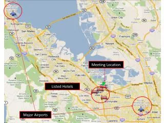
Office of Airports. Airport Geometrics Airports Division, Western Pacific Region. 3 Sets of Aviation Standards. Airport Imaginary Surfaces - Part 77 Airport Design Standards (A.C.s) Terminal Instrument Procedures (TERPS). 3 Airport Assurances.

E N D
Office of Airports Airport Geometrics Airports Division, Western Pacific Region
3 Sets of Aviation Standards • Airport Imaginary Surfaces - Part 77 • Airport Design Standards (A.C.s) • Terminal Instrument Procedures (TERPS)
3 Airport Assurances • -Assurance 19, Operation and Maintenance: The sponsor will not cause or permit any activity or action on the obligated airport that would interfere with its use for airport purposes. • - Assurance 20, Hazard Removal and Mitigation: The sponsor will prevent the establishment or creation of any future airport hazard. • - Assurance 29, Airport Layout Plan (ALP): The sponsor will not make or permit any changes to the airport or any of its facilities that are not in conformity with the FAA-approved ALP or which might in the opinion of the FAA adversely affect the safety, utility, or efficiency of the airport.
14 CFR Part 77 • Defines “obstructions to air navigation” • Requires notice to FAA prior to construction • Procedures for studies and determinations • Hazards to Air Navigation
Part 77 Imaginary Surfaces • Standards for determining obstructions • Applies to objects: • natural growth • terrain • permanent or temporary construction or alteration • including temporary equipment used for construction
Obstructions and Hazards • Obstruction - any object that penetrates any of the Imaginary Surfaces • Hazard - Obstruction that is determined through an airspace study to substantially affect the safe passage of an aircraft • All Hazards are Obstructions • Not all Obstructions are Hazards
FAR 77 IMAGINARY SURFACES PPrimary AApproach T Transitional HHorizontal CConical
Approach Surface Transitional Surface Horizontal Surface Conical Surface Transitional Surface Primary Surface FAR 77 IMAGINARY SURFACES (Cut-Away View)
FAR 77 IMAGINARY SURFACES (Top View) Transitional Surface Primary Surface Approach Surface Horizontal Surface Conical Surface Transitional Surface
Primary Surface • Primary surface • - Centered around runway • - Extends 200 ft beyond the runway end • - Width varies from 250 ft to 1000 ft
Primary Surface Width - 250 ft to 1000 ft Length - extends 200 ft from runway end
Approach Surface • Begins at end of Primary Surface • Inner edge - same width as Primary Surface • Outer edge varies - 1250 ft to 16,000ft • Length varies - 5,000 or 10,000ft • Slope varies - 20:1 34:1 50:1
APPROACH SURFACE W1 Primary Surface length W2 30 200’ Approach Surface Runway Approach Surface 50:1
In computing obstruction heights, allow: a. Public Roads 15 ft b. Interstate Highway 17 ft c. Railroad 23 ft d. Waterway Tallest Object Road Interstate Highway Railroad Waterway 15 ft 17 ft 23 ft tallest object
Transitional Surface • Extends outward and upward at right angles to runway centerline • Starts at outside edge of the Primary Surface • Slope is 7:1
Transitional Surface Primary Surface Approach Surface Approach Surface Transitional Surface Transitional Surface 7:1 Primary Surface Runway
Transitional Surfaces Horizontal Surface 150 feet Slope 7:1 Transitional Surface Primary Surface
Airport Design Standards • Runway Safety Areas (RSA) • Rectangular ground surface around runway • Runway Object Free Area (ROFA) • Rectangular ground surface around runway and safety area • Obstacle Free Zone (OFZ) • Volume of airspace above runway
Airport Reference Code (ARC) • The ARC is a coding system to relate airport design criteria to the operational and physical characteristics of the aircraft intended to use the airport. • A. Aircraft approach category (relates to aircraft approach speed) • B. Airplane design group (relates to airplane wingspan)
RUNWAY OBJECT FREE AREA RUNWAY SAFETY AREA STRUCTURAL PAVEMENT SHOULDER SHOULDER RUNWAY AREA CROSS SECTION
Runway Safety Area • Width and length based on the ARC (both approach and wingspan) • Found in Tables 3-1, 3-2, & 3-3 in • AC 150/5300-13 • Width and length vary (based on ARC) from 60 ft either side of centerline and 240 ft beyond runway end to 250 ft either side of centerline to 1000 ft beyond the runway.
Runway Safety Area 27 9 Width varies from 120 ft wide (60 ft either side of Center Line) to 500 ft, depending on aircraft design group. Length = 2 x Width
RSA Object Clearing Criteria • Free of objects except those fixed by function: • objects over 3 inches must be frangible at no more than 3 inches • Manholes must be constructed at grade • Personnel and Equipment may not be in RSA during aircraft operations
Runway Object Free Area • Two dimensional ground area • Surrounds runways, taxiways, and taxilanes • Clear of Objects except those fixed by function
Runway Object Free Area Width ranges from 250 ft wide (125 ft either side of CL) to 800 ft wide Length ranges from 240 ft long to 1000 ft
ROFA Clearing Criteria • Acceptable: • Objects for air navigation • Aircraft ground maneuvering purposes • Taxiing and holding aircraft • Not Acceptable: • Objects not essential for air navigation or aircraft maneuvering purposes • Parked aircraft • Agricultural Operations
Comparison of RSA with ROFA ARC C-III, Airplane Design Group III (Wingspan 79 ft to 117 ft) and Approach Category C (121 knots to 140 knots) e.g. B-737 OFA - 800 ft wide 1000 ft beyond end of runway RSA - 500 ft wide 1000 ft beyond end of runway
Obstacle Free Zone • 3 Dimensional Plane - Volume of Airspace • Precludes taxiing and parked planes and object penetration • NAVAIDS fixed by function but frangible • Rnwy OFZ: Inner-approach OFZ: Inner-transitional OFZ
Dimensions of OFZ Extends 200 ft beyond the end of the runway Width varies from 120 ft to 400 ft depending on size of aircraft and approach speed
OFZ Clearing Criteria • Not Acceptable: • Taxiing aircraft • Parked aircraft • NavAids that are not frangible
Comparison of RSA, ROFA, OFZ RSA ROFA OFZ
Runway Protection Zone L W1 - 250 to 1000 W2 - 450 to 1750 L - 1000 to 2500 W2 W1 ROFA 200 ft
Inner-Transitional OFZ Visual & Runways not lower than 3/4 sm vis No ALS ALS 50:1 150 ft above airport elev. Rnwy OFZ
Inner-Transitional OFZ Large aircraft and lower than 3/4 mi vis 150 ft H Slope varies: Cat I 6:1 Cat II/III 5:1 then 6:1 Rnwy OFZ
B A A B SECTION A - A 150 FEET ABOVE ARPT ELEV SECTION B - B OFZ FOR VISUAL RUNWAYS & RUNWAYS >= 3/4 MILE
B A A B SECTION A - A 150 FEET ABOVE ARPT ELEV 3:1 SECTION B - B OFZ SERVING SMALL AIRPLANES < 3/4 MILE
B A A B SECTION A - A 150 FEET ABOVE ARPT ELEV 6:1 H SECTION B - B OFZ SERVING LARGE AIRPLANES < 3/4 MILE
RUNWAY OBJECT FREE AREA CONTROLLED ACTIVITY AREA RUNWAY PROTECTION ZONE CONFIGURATION
LENGTH W 1 W 2 RUNWAY PROTECTION ZONE
RPZ VISUAL & >= 1 MILE CATEGORY C & D W 1 500’, L 1,700’, W 2 1,010’ RUNWAY SAFETY AREA RUNWAY OBJECT FREE AREA RPZ < 3/4 MILE ALL AIRCRAFT W1 1,000’, L 2,500’, W2 1,750’ RPZ, RSA, & ROFA SERVING LARGE AIRCRAFT
PRIMARY SURFACE For Utility Hard Surface Runway 500’ if non- precision instrument runway 250’ if visual runway Runway 200' 200'
Controlling Object Actual slope of 40:1 Clear 34:1 slope Controlling Object that prevents a 50:1 slope
COMMON IMPACTS TO IMAGINARY SURFACES APPROACH SLOPE PRIMARY SURFACE
COMMON IMPACTS TO IMAGINARY SURFACES 7:1 TRANSITIONAL SLOPE PRIMARY SURFACE
FILING FAA FORM 7460-1 • https://oeaaa.faa.gov/oeaaa/external/portal.jsp • -If first time, register as new user first then log in to file your airspace case proposal • -Upload your sketch, in pdf format • -Verify your case by mapping • -instructions included in the portal site • -30 days for FAA to issue determination • -Determination good for 18 months • -Before case expires, can be extended for another 18 months
Common mistakes • -Geographical coordinates are not correct or are not of sufficient accuracy, Lat/Long coordinates need to be to the nearest 0.01 sec • -Case filed to late, usually occurs with temporary cranes • -Not enough points given for FAA to properly evaluate
Reference Material • FAR Part 139 Certification of Land Airports • FAA Order 5010.4, Airport Safety Data Program • 14 CFR Part 77, Objects Affecting Navigable Airspace • AC 150/5300-13, Airport Design • FAA Order 5280.5, Airport Certification Program Handbook
Reference Material • AC 70/7460-2, Proposed Construction or Alteration of Objects that May Affect the Navigable Airspace • AC 70/7460-1, Obstruction Marking and Lighting • 14 CFR Part 77, Objects Affecting Navigable Airspace