Download
1 / 23
240 likes | 526 Views
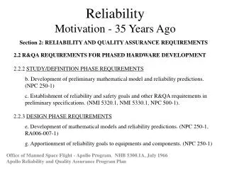
Reliability Motivation - 35 Years Ago. Section 2: RELIABILITY AND QUALITY ASSURANCE REQUIREMENTS. 2.2 R&QA REQUIREMENTS FOR PHASED HARDWARE DEVELOPMENT 2.2.2 STUDY/DEFINITION PHASE REQUIREMENTS b. Development of preliminary mathematical model and reliability predictions. (NPC 250-1)

E N D
ReliabilityMotivation - 35 Years Ago Section 2: RELIABILITY AND QUALITY ASSURANCE REQUIREMENTS • 2.2 R&QA REQUIREMENTS FOR PHASED HARDWARE DEVELOPMENT • 2.2.2 STUDY/DEFINITION PHASE REQUIREMENTS • b. Development of preliminary mathematical model and reliability predictions. (NPC 250-1) • c. Establishment of reliability and safety goals and other R&QA requirements in preliminary specifications. (NMI 5320.1, NMI 5330.1, NPC 500-1). • 2.2.3 DESIGN PHASE REQUIREMENTS • e. Development of mathematical models and reliability predictions. (NPC 250-1, RA006-007-1) • g. Apportionment of reliability goals to equipments and components. (NPC 250-1) Office of Manned Space Flight - Apollo Program. NHB 5300.1A, July 1966 Apollo Reliability and Quality Assurance Program Plan
LEVEL RELIABILITY ANALYSIS AND MODELING ACTIVITY HARDWARE I . . . . . . . . . . . . . . . . . . . . . . . . . . . . . . . . . . . . . . . . . . . . . . . . . . . . . . . . . . . . . . . . . . . . . . . . II . . . . . . . . . . . . . . . . . . . . . . . . . . . . . . . . . . . . . . . . . . . . . . . . . III . . . . . . . . . . . . . . . . . . . . . . . . . . . . . . . . . . IV . . . . . . . . . . . . . . . . . . Missions Mission/Launch Vehicle/Spacecraft/ Ground Support Systems/Stage/ Module/Subsystem Apollo Mission Reliability Estimates Apollo Program Office - R&QA Model Integration Launch Vehicle/ Spacecraft/Ground Support Systems/ Stage/Module/ Subsystem/ Black Box Center Estimates SC LV LC GOSS Apollo Program Office - R&QA Review Stage/Module/ Subsystem/ Black Box/ Component Contractor Reliability Estimates Center Review Subsystem/ Black Box/ Component/Part Subcontractor and Design Group Estimates Contractor Review Reliability - 35 Years Ago Office of Manned Space Flight - Apollo Program. NHB 5300.1A, July 1966 Apollo Reliability and Quality Assurance Program Plan
Reliability • Introduction to Reliability • Historical Perspective • Current Devices • Trends
Failure rate, Infant Mortality Useful life Wear out Constant Time The Bathtub Curve
The Bathtub Curve (2) What is the "bathtub" curve? In the 1950’s, a group known as AGREE (Advisory Group for the Reliability of Electronic Equipment) discovered that the failure rate of electronic equipment had a pattern similar to the death rate of people in a closed system. Specifically, they noted that the failure rate of electronic components and systems follow the classical “bathtub” curve. This curve has three distinctive phases: 1. An “infant mortality” early life phase characterized by a decreasing failure rate (Phase 1). Failure occurrence during this period is not random in time but rather the result of substandard components with gross defects and the lack of adequate controls in the manufacturing process. Parts fail at a high but decreasing rate. 2. A “useful life” period where electronics have a relatively constant failure rate caused by randomly occurring defects and stresses (Phase 2). This corresponds to a normal wear and tear period where failures are caused by unexpected and sudden over stress conditions. Most reliability analyses pertaining to electronic systems are concerned with lowering the failure frequency (i.e., const shown in the Figure) during this period. 3. A “wear out” period where the failure rate increases due to critical parts wearing out (Phase 3). As they wear out, it takes less stress to cause failure and the overall system failure rate increases, accordingly failures do not occur randomly in time.
Introduction to Reliability • Failure in time (FIT) Failures per 109 hours ( ~ 104 hours/year ) • Acceleration Factors • Temperature • Voltage
EA/kT ttf = C • e Introduction to Reliability (cont'd) Most failure mechanisms can be modeled using the Arrhenius equation. ttf - time to failure (hours) C - constant (hours) EA - activation energy (eV) k - Boltzman's constant (8.616 x 10⁻⁵eV/°K) T - temperature (ºK)
Introduction to Reliability (cont'd)Acceleration Factors ttfL A.F. = ------ ttfH A.F. = acceleration factor ttfL = time to failure, system junction temp (hours) ttfH = time to failure, test junction temp (hours)
Introduction to Reliability (cont'd)Activation Energies Failure Mechanism EA(eV) Oxide/dielectric defects 0.3 Chemical, galvanic, or electrolytic corrosion 0.3 Silicon defects 0.3 Electromigration 0.5 to 0.7 Unknown 0.7 Broken bonds 0.7 Lifted die 0.7 Surface related contamination induced shifts 1.0 Lifted bonds (Au-A1 interface) 1.0 Charge injection 1.3 Note: Different sources have different values - these values just given for examples.
0.07/kT = 0.4 • e Acceleration Factor - VoltageOxides and Dielectrics • Large acceleration factors from increase in electric field strength A.F. = 10 • / (MV / cm) k - Boltzman's constant (8.616 x 10⁻⁵eV/°K) T - temperature (ºK)
Acceleration Factor: Voltage Median-time-to-fail of unprogrammed antifuse vs. 1/V for different failure criteria with positive stress voltage on top electrode and Ta = 25 °C.
Integrated Circuit ReliabilityHistorical Perspective Application Reliability • Apollo Guidance Computer < 10 FITs • Commercial (1971) 500 Hours • Military (1971) 2,000 Hours • High Reliability (1971) 10,000 Hours • SSI/MSI/PROM 38510 (1976) 44-344 FITs • MSI/LSI CICD Hi-Rel (1987) 43 FITs
Device and Computer Reliability1960's Hi-Rel Application • Apollo Guidance Computer • Failure rate of IC gates: < 0.001% / 1,000 hours ( < 10 FITS ) • Field Mean-Time-To-Failure ~ 13,000 hours • One gate type used with large effort on screening, failure analysis, and implementation.
Device Reliability:1971 Reliability Level of Representative Parts and Practices MTBF (hr) Commercial 500 Military 2,000 High Reliability 10,000 (104 hours)
MIL-M-38510 Devices (1976) Circuit Types Description FITS 5400 Quad, 2-input NAND 60 5482 2-bit, full adder 44 5483 4-bit, full adder 112 5474 Dual, D, edge-triggered flip-flop 72 54S174 Hex, D, edge-triggered flip-flop 152 54163 4-bit synchronous counter 120 4049A Inverting hex buffer 52 4013A Dual, D, edge-triggered flip-flop 104 4020A 14-stage, ripple carry counter 344 10502 Triple NOR (ECL) 80 HYPROM512 512-bit PROM 280
Harris CICD Devices (1987) • Circuit Types • HS-6504 - 4k X 1 RAM HS-8155/56 - 256 x 8 RAM • HS-6514 - 1k x 4 RAM HS-82C08RH - Bus Transceiver • HS-3374RH - Level Converter HS-82C12RH - I/O Port • HS-54C138RH - Decoder HS-8355RH - 2k x 8 ROM • HS-80C85RH - 8-bit CPU • Package Types • Flat Packs (hermetic brazed and glass/ceramic seals) • LCC • DIP • FITS @ 55°C, Failure Rate @ 60% U.C.L. • 43.0
Actel FPGAs Technology FITS # Failures Device-Hours (m) 2.0/1.2 33 2 9.4 x 10⁷ 1.0 9.0 6 6.1 x 10⁸ 0.8 10.9 1 1.9 x 10⁸ 0.6 4.9 0 1.9 x 10⁸ 0.45 12.6 0 7.3 x 10⁷ 0.35 19.3 0 4.8 x 107 RTSX 0.6 33.7 0 2.7 x 10⁷ 0.25 88.9 0 1.0 x 10⁷ 0.22 78.6 0 1.2 x 10⁷
Xilinx FPGAs • XC40xxXL • Static: 9 FIT, 60% UCL • Dynamic: 29 FIT, 60% UCL • XCVxxx • Static: 34 FIT, 60% UCL • Dynamic: 443 FIT, 60% UCL
UTMC and Quicklogic • FPGA • < 10 FITS (planned) • Quicklogic reports 12 FIT, 60% UCL • UT22VP10 UTER Technology, 0 failures, 0.3 • Antifuse PROM • 64K: 19 FIT, 60% UCL • 256K: 76 FIT, 60% UCL
RAMTRON FRAMs Technology FITS # Failures # Devices Hours Device-Hours 1608 (64K) 1281 1 100 103 105 4k & 16K Serial 37 152 4257 103 4.3 x 10⁶ Note: Applied stress, HTOL, 125ºC, Dynamic, VCC=5.5V. 1 The one failure occurred in less then 48 hours. The manufacturer feels that this was an infant mortality failure. 2 12 failures detected at 168 hours, 3 failures at 500 hours, and no failures detected after that point.
Skylab Lessons Learned 58. Lesson: New Electronic Components Avoid the use of new electronic techniques and components in critical subsystems unless their use is absolutely mandatory. Background: New electronic components (resistors, diodes, transistors, switches, etc.) are developed each year. Most push the state-of-the-art and contain new fabrication processes. Designers of systems are eager to use them since they each have advantages over more conventional components. However, being new, they are untried and generally have unknown characteristics and idiosynchracies. Let some other program discover the problems. Do not use components which have not been previously used in a similar application if it can be avoided, even at the expense of size and weight.