Download
1 / 57
580 likes | 782 Views
CDMA OVERVIEW. MULTIPLE ACCESS SPREADING SPECTRUM CODES IN CDMA CDMA CHANNEL STRUCTURE POWER CONTROL DIVERSITY HAND OFFS. ○ TWO METHODS FOR SUBSCRIBER CONNECTION. Subscriber. Exchange. Copper Local Loop. Subscriber. Exchange. BSC. FSU. BTS. Wireless Local Loop.

E N D
MULTIPLE ACCESS • SPREADING SPECTRUM • CODES IN CDMA • CDMA CHANNEL STRUCTURE • POWER CONTROL • DIVERSITY • HAND OFFS
○ TWO METHODS FOR SUBSCRIBER CONNECTION Subscriber Exchange Copper Local Loop Subscriber Exchange BSC FSU BTS Wireless Local Loop
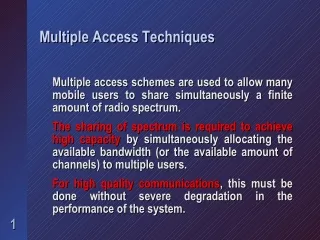
WHAT IS MULTIPLE ACCESS? • NUMBER OF USERS ACCESS AND SHARE • TRANSMISSION MEDIUM • BANDWIDTH AVAILABLE • FOR COMMUNICATION AT THE SAME TIME.
MULTIPLE ACCESS • MULTIPLE SIMULTANEOUS TRANSMISSIONS. • SHARING FINITE SPECTRUM AMONG LARGE NO. OF SIMULTANEOUS USERS. • NO PRE-ASSIGNED CIRCUIT TO ANY USER. • ANY USER CAN ACCESS ANY CIRCUIT AND MAY ACCESS DIFFERENT CIRCUITS FOR DIFFERENT CALLS. • DEMAND ASSIGNED CIRCUITS ON FIRST COME FIRST SERVE BASIS. • PRIVACY. • TRUNKING EFFICIENCY; THEREBY IMPROVEMENT IN SYSTEM CAPACITY.
MULTIPLE ACCESS METHODS Frequency Division Multiple Access (FDMA) FDMA is a multiple access method in which users are assigned specific frequency bands. The user has sole right of using the frequency band for the entire call duration. Time Division Multiple Access (TDMA) In TDMA an assigned frequency band shared among a few users. However, each user is allowed to transmit in predetermined time slots. Hence, channelization of user is achieved through separation in time.
CODE DIVISION MULTIPLE ACCESS (CDMA) LARGE NUMBER OF TRANSMISSIONS ARE COMBINED ON THE SAME RF CHANNEL AT THE SAME TIME BUT ARE SEPERATED BY “CODES”.
RK/TR/ALTTC 7 WILL/ overview MULTIPLE ACCESS TECHNIQUES F R E Q U E N C Y FDMA TDMA CDMA TIME
CDMA: Code Division Multiple CDMA is a method in which users occupy the same time and frequency allocations, and are channelized by unique assigned codes. The signals are separated at the receiver by using a correlator that Access accepts only signal energy from the desired channel. Undesired signals contribute only to the noise. A CDMA system uses effective power control process.
Advantages:- • The main advantages of this technology are: • Fast Network deployment. • Reduced service interruptions. • Low Maintenance & operational cost. • Better system coverage flexibility • Higher capacity • Easy transition to mobile services.
Salient Features of CDMA • It is an advanced comm. Technology. • It has Anti-jam and security features. • Large capacity as compared to other Technology. • like FDMA and TDMA. • It uses spread spectrum technology. • Better use of the multipath. • Frequency Reuse.
Frequency Reuse In CDMA reuse patterns are not required. Subscriber in every cell can use the same frequency at the same time. Subscriber is discriminated from another by the assignment of a unique code to every conversation. In GSM freq. Reuse pattern of 7 is used.
E F D B E F C G C B D A G C F D A B E F D C B E A G C B Frequency Reuse pattern of 7 (FDMA)
A A A A A A A A A A A A A A A A A A A A A A A A A A A A CDMA Frequency Reuse
Frequency Bands CDMA 824- 849 MHz 869- 894 MHz PCS 1850- 1910 MHz 1930- 1990 MHz
CDMA channel is 1.25 MHz wide and there is a separation of 45 MHz in the forward and the reverse channel in case of cellular band & and 80 MHz in case of PCS band. 45 MHz 1.25 MHz 1.25 MHz CDMA Channel in PCS band 80 MHz 1.25 MHz 1.25 MHz CDMA Channel in 800 MHz band
SPREADING SPECTRUM • Shannon’s Equation • C= W Log (1+S/N) • Where C=Capacity (bps) • W=Bandwidth • S=Signal Power • N=Noise Power • Shannon’s Capacity Equation is basis for spread spectrum. System with large band width can operate at very low SNR level & can provide acceptable data rate per user. • Therefore in CDMA • All users uses same 1.25 MHz spectrum. • Each user has unique Digital code identifier. • Digital codes separate users to avoid interference.
SPREAD SPECTRUM TECHNIQUES • Frequency Hopped Spread Spectrum: • Spreading can also be achieved by hopping the narrowband information signal over a set of frequencies. The type of spreading can be classified as fast or slow depending upon the rate of hopping to the rate of information. • 2. Direct Sequence Spread Spectrum: • The information signal is inherently narrowband, on the order of less than 10KHz. The energy from this narrowband signal is spread over a much larger bandwidth by multiplying the information signal by a wideband spreading code. DSS technique is used in the IS-95 CDMA cellular system.
Direct Sequence Spread using Walsh code • Consist of 64 orthogonal codes each 64 bits long • Spreads spectrum to 1.2288 M bps from 9.6 Kbps Channel Capacity • C=W log (1+S/N) • Increasing BW improves Signal Transmission with lower S/N Narrow Band Waveform Power Spectral Density Noise Level -------------------------------------------------------------------------------------- Spread Waveform Frequency
PROCESSING GAIN One of the major advantages with an SS system is its robustness to interference. The system processing gain Gp quantifies the degree of interference rejection. The system processing gainis the ratio of RF bandwidth to the information rate: Gp =W/R =1.2288x 10⁶ /9.6 x 103 =128 dBgain =10log10 128 =21
Spread spectrum principle: Originally spread spectrum radio technology was developed for military use to counter the interference by hostile jamming. The broad spectrum of the transmitted signal gives rise to”spread spectrum”. A spectrum signal is generated by modulating the radio frequency (RF) signal with a code consisting of different pseudo random binary sequences, which is inherently resistant to noisy signal environment.
A number of spread spectrum RF signals thus generated share the same frequency spectrum and thus the entire bandwidth available in the band will be used by each of the users using same frequency at the same time. On the receive side only the signal energy with the selected binary sequence code is accepted and information content is recovered. The other user signals, whose codes do not match contribute only the noise and are not “de-spread” back in bandwidth. This transmission and reception of signals differentiated by “codes” using the same frequency simultaneously by a number of users is known as code Division Multiple Access (CDMA).
Techniques as opposed to conventional method of Frequency Division Multiple Access and Time Division Multiple Access. In the fig. It has been tried to explain that how the base band signal of 9.6 kbps is spread using a long pseudo-random Noise(PN) source to occupy entire bandwidth of 1.25 Mhz. At the receiving end this signal will have interference from signals of other users of the same cell, user different cells and interference from other noise sources. All these signals get combined with the desired signal but using a correlator and correct PN code, the original data can be reproduced back.
ORTHOGONAL SPREADING:- RX TX 01101001100101100110 USER OUTPUT 1 0 0 1 1 USER INPUT 1 0 0 1 1 Cell Cell 10011001100110011001 CODE 10011001100110011001 CODE User Input 1 0 0 1 1 Spreading Sequence 1001 1001 1001 1001 1001 TX Data 0110 1001 1001 0110 0110
0110 1001 1001 0110 0110 Rx Data 1001 1001 1001 1001 1001 Correct Function 1111 0000 0000 1111 1111 1 0 0 1 1 Decoding using correct Orthogonal Function
0110 1001 1001 0110 0110 Rx Data 0101 0101 0101 0101 0101 Incorrect Function 0011 1100 1100 0011 0011 ? ? ? ? ? Decoding using incorrect Orthogonal Function
Spreading Codes • cdmaOne systems use two types of code sequences: • Orthogonal sequences (Walsh codes). • Pseudorandom Noise (PN) sequences. • Long codes (242 =4400 Billion) • Short codes (215 =32768)
Walsh Codes:- In CDMA the traffic channels are separated by Unique “Walsh” code. These are (a)64 codes of 64 Bit Length. (b)Forwarded traffic channel Codes. (c)All codes are orthogonal to each other. (d)These codes provide Isolation betweenmultiple signals transmitted by basestations
The basic concept behind creation of the code is as follows: • Repeat the function right • Repeat the function below • Invert function (diagonally) Fig: Seed 0 0 0 0 0 0 0 0 1 0 1 0 1 0 0 1 1 0 1 1 0
By using this technique we create a set of 64 such codes of 64 bit length which is known as Walsh codes. All such codes are orthogonal to each other. The individual subscriber now can start communication using one of these codes. These codes are traffic channel codes and are used for orthogonal spreading of the information in the entire bandwidth. Orthogonality provides nearly perfect isolation between the multiple signals transmitted by the base station.
PN Code Generation • PN Codes are generated from prime polynomials using modulo-2 arithmetic. • State machines generating PN Codes consists of shift registers & XOR gates. • The length of the PN Code is equal to 2 -1 ( N= no. of shift registers). 0 0 1 out Output will be a 7-digit sequence that repeats continually 1001011 N
0 0 1 1 0 1 1 1 1 0 0 0 0 1 0 0 1 1 1 1 1 1 0 0 1 0 1 1 Sequence = 1001011 1001011
PN offset (Masking) • Masking will cause the generator to produce the same sequence but offset in time. • Masking provides the shift in time for PN codes. • Different masks corresponds to different time shifts. • ESN are used as masks for users on the traffic channels.
LONG CODE (a) 242Bits polynomials. (b) Forwarded channel Data (traffic and paging chls) scrambled. (c) Provides channelizations for the reverse chls. (d) This code is unique for every subscriber. (e) It is known as user address mask or user identification. (f) Subscriber are differentiated as no two same codes are used. (g) Repeats every 41 days (at a clock rate of 1.2288 Mcps)
SHORT CODES • (a) This PN sequence is based on 215 • characteristics polynomial. • (b) Differentiates cells and sectors. • (c) Identifies cells and sectors. • (d) Consist of codes for I & Q chls. • (e) Each cell uses different codes. • (f) Repeats every 26.67 msec (at a clock • rate of 1.2288 Mcps)
CDMA Channels Forward Link Channels Pilot Channel Sync Channel Paging Channels Traffic Channels Reverse Link Channels Access Channels Traffic Channels
CDMA CHLARCHITECTURE • Pilot channel (W0) • The pilot is used by the subs unit to obtain initial system synchronization and to distinguish cell sites. Every sector of every cell site has a unique pilot channel. • Transmitted constantly. • Allows the mobile to acquire the system. • Provides mobile with signal strength comparison. • Approximately 20% of the radiated power is in the pilot. • Has unique PN Offset(215 ) for each cell or sector.
Sync channel(W32) • Used during system Acquisition stage. Sync chl provides the subs unit with network information related to cell site identification, pilot transmit power & cell site PN offset. • Used by mobile to synchronize with the system • Transmits sync message with • - Pilot PN offset - System time • - Long PN code - System ID • - Network ID - Paging chl data rate • Tx at 1200 bps
PAGING CHLS(W1-W7) • On this chl base station can page the subs unit and it can send call set-up and traffic chl assignment information. • Means of communication between base to mobile station. • Paging CHL data Rates can be 2.4,4.8 or 9.6 Kbps. • CDMA assignment has 7 paging CHLs. • Each paging CHL supports 180 pages per set. • Total pages/ CDMA RF chl = 1260
Provides mobile with • - System Parameter message - Neighbour list • - Access Parameter list - CDMA Channel list • Used by base station to : • - Page mobile - Transmit overhead information • - Assign mobile to traffic channel
Traffic Channels ( W8-W31 & W33-W63) The traffic chl carries the actual call. That is, the voice and control information between the subs unit & base station. TX upto 9.6kbps on rate set 1 and upto 14.4kbps on rate set 2.
Access CHLS. • (a)Provides communication from Mobile to base station when mobile is not using traffic Chl. The access chl is used for call origination & for response to pages, orders & registration requests. It is paired with corresponding paging chl. • (b) Each Access CHL use long PN code. • Base station responds to transmission on aparticular Access CHL. • Mobile responds to base station message by emitting on Access CHL. • Tx at 4800bps
cdmaOne Modulation Information A/D Vocoder Information Bits FEC Code symbols Chips Spreading code generator PSK Spreader
Forward Traffic Channel Generation I PN 9600 bps 4800 bps 2400 bps 1200 bps Rate set 1 Power Control bit 19.2 ksps Convolutional Encoder & Repetition Block interleaver 19.2 ksps User Address Mask (ESN) Long Code PN 1.2288 decimator decimator O PN Wt R=1/2 1.2288 Mcps Rate set 2 14400 bps 7200 bps 3600 bps 1800 bps R=3/4 Mcps 800bps 64:1 24:1
Reverse Traffic Channel Generation I PN 9600 bps 4800 bps 2400 bps 1200 bps Rate set 1 28.8 ksps Convolutional Encoder & Repetition Block interleaver User Address Mask (ESN) Long Code PN 1.2288 O PN Orthogonal Modulation R=1/3 307.2 KHz Data Burst Rand. 1.2288 Mcps Rate set 2 14400 bps 7200 bps 3600 bps 1800 bps R=1/2 Mcps
Rake receiver • CDMA mobiles use rake receivers. The rake receiver essentially a set of four or more receivers (or fingers). One of the receivers constantly searches for different multipaths and helps to direct the other three fingers to lock onto strong multipath signals. • Allows combined reception of up to three different paths. • Provides searcher receiver to identify changes in path characteristics/new cells. • Provides both path diversity and frequency diversity.
Correlator 1 combiner Correlator 2 Correlator 3 Searcher Correlator CDMA mobile rake receiver
Rake receiver T0 T1 T2 T3 W3 W0 W1 W2 Summing Circuit OUTPUT ANTENNA DELAY TAPS TAP WEIGHTS
VOCODER Disadvantage of Digital Comm. System Bandwidth expansion of digitally sampled speech Solution : Variable rate vocoder S(t) S(n) P(n) A/D Speech Encoder CDMA Modem RF Microphone Mobile RF Channel S(t): Input analog Speech S(n): Input digitized speech blocked into 20 msec frames P(n): Encoded packets every 20 msec representing parameters of speech such as spectral envelope, pitch, energy and phases S(n): Reconstructed digital speech S(t): Reconstructed analog speech S(t) S(n) P(n) D/A Speech Decoder CDMA Modem RF Speaker
Hand offs • Softer handoff • Multi sector hand off (Intra BTS) • Can have upto 3or 6 sectors involved (same cell) • Voice data is combined at cell and passed as one cell to BSC • Make before break • Soft handoff • Multi-cell Handoff (Inter BTS) • Can have upto 3 cells involved (same FA) • Each cell provides voice data to BSC • Voice data is selected at SVC to vocoder in BSC • Make before break