Download
1 / 57
590 likes | 755 Views
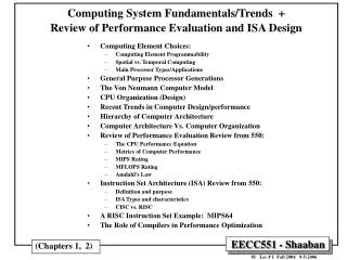
Lesson 5: Processor Design. Topic 1 – Methods and Concepts. Introduction. References: -Modern Processor Design Book ( pp. 1 – 16) - Computer Organization and Design Book (pp. 54- 89). While introducing this topic we will focus on these points: Evolution of microprocessors

E N D
Lesson 5: Processor Design Topic 1 – Methods and Concepts EE37E 2005
Introduction References: -Modern Processor Design Book ( pp. 1 – 16) - Computer Organization and Design Book (pp. 54- 89) EE37E 2005
While introducing this topic we will focus on these points: • Evolution of microprocessors • Instruction set processor design • Principles • Microprocessors are Instruction set processors (ISPs). • An ISP executes instructions from a predefined instruction set. • A microprocessor’s functionality is fully characterized by the instruction set it is capable of executing. • This predefined instruction set is also called the instruction set architecture. EE37E 2005
An ISA serves as an interface between software and hardware. • In terms of processor design methodology, an ISA is the specification of the design while the microprocessor or ISP is the implementation of a design. EE37E 2005
Memory Controller NICs Memory Computer System Components 1000MHZ - 3 GHZ (a multiple of system bus speed) Pipelined ( 7 -21 stages ) Superscalar (max ~ 4 instructions/cycle) single-threaded Dynamically-Scheduled or VLIW Dynamic and static branch prediction L1 L2 L3 CPU Examples: Alpha, AMD K7: EV6, 400MHZ Intel PII, PIII: GTL+ 133MHZ Intel P4 800MHZ Caches SDRAM PC100/PC133 100-133MHZ 64-128 bits wide 2-way inteleaved ~ 900 MBYTES/SEC Double Date Rate (DDR) SDRAM PC3200 400MHZ (effective 200x2) 64-128 bits wide 4-way interleaved ~3.2 GBYTES/SEC (second half 2002) RAMbus DRAM (RDRAM) PC800, PC1060 400-533MHZ (DDR) 16-32 bits wide channel ~ 1.6 - 3.2 GBYTES/SEC ( per channel) System Bus Support for one or more CPUs adapters I/O Buses Example: PCI-X 133MHZ PCI, 33-66MHZ 32-64 bits wide 133-1024 MBYTES/SEC Memory Bus Controllers Disks Displays Keyboards Networks I/O Devices: Fast Ethernet Gigabit Ethernet ATM, Token Ring .. North Bridge South Bridge Chipset EE37E 2005
Memory Controller NICs Memory Computer System Components Enhanced CPU Performance & Capabilities: • Support for Simultaneous Multithreading (SMT): Alpha EV8. • VLIW & intelligent compiler techniques: Intel/HP EPIC IA-64. • More Advanced Branch Prediction Techniques. • Chip Multiprocessors (CMPs): The Hydra Project. IBM Power 4,5 • Vector processing capability: Vector Intelligent RAM (VIRAM). • Or Multimedia ISA extension. • Digital Signal Processing (DSP) capability in system. • Re-Configurable Computing hardware capability in system. SMT CMP Memory Latency Reduction: Conventional & Block-based Trace Cache. L1 L2 L3 CPU Caches Integrate Memory Controller & a portion of main memory with CPU: Intelligent RAM Integrated memory Controller: AMD Opetron IBM Power5 System Bus adapters I/O Buses Memory Bus Controllers Disks (RAID) Displays Keyboards Networks North Bridge South Bridge I/O Devices: Chipset EE37E 2005
Recent Trends in Computer Design • The cost/performance ratio of computing systems have seen a steady decline due to advances in: • Integrated circuit technology: decreasing feature size, • Clock rate improves roughly proportional to improvement in • Number of transistors improves proportional to (or faster). • Architectural improvements in CPU design. • Microprocessor systems directly reflect IC improvement in terms of a yearly 35 to 55% improvement in performance. • Assembly language has been mostly eliminated and replaced by other alternatives such as C or C++ • Standard operating Systems (UNIX, NT) lowered the cost of introducing new architectures. • Emergence of RISC architectures and RISC-core architectures. • Adoption of quantitative approaches to computer design based on empirical performance observations. EE37E 2005
Microprocessor Architecture Trends CMPs (SMT) SMT/CMPs (e.g. IBM Power5 in 2004) EE37E 2005
Evolution of microprocessors “Graduation Window” Alpha 21264: 15 million Pentium Pro: 5.5 million PowerPC 620: 6.9 million Alpha 21164: 9.3 million Sparc Ultra: 5.2 million Moore’s Law • CMOS improvements: • Die size: 2X every 3 yrs • Line width: halve / 4-7 yrs Figure1: Evolution of microprocessors EE37E 2005
Three decades of the history of microprocessors tell a truly remarkable story of advances in the computer industry (Table 1). Table 1. The amazing decades of the evolution of microprocessors EE37E 2005
Application Operating System Compiler Firmware Instruction Set Architecture Instr. Set Proc. I/O system Datapath & Control Digital Design Circuit Design Layout Hierarchy of Computer Architecture High-Level Language Programs Assembly Language Programs Software Machine Language Program Software/Hardware Boundary Hardware Microprogram Register Transfer Notation (RTN) Logic Diagrams Circuit Diagrams EE37E 2005
Instruction Set Processor Design • Critical to an ISP is the instruction set architecture, which specifies the functionality that must be implemented by the instruction set processor (ISP). EE37E 2005
The Design Process • "To Design Is To Represent“ • Design activity yields description/representation of an object • Traditional craftsman does not distinguish between the conceptualization and the artifact • Separation comes about because of complexity • Concept is captured in one or more representation languages • This process IS design • Design Begins With Requirements • Functional Capabilities: what it will do • Performance Characteristics: Speed, Power, Area, Cost, . . . EE37E 2005
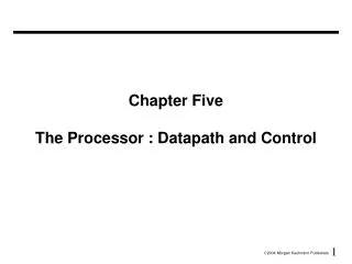
Design Process (cont.) CPU • Design Finishes As Assembly • Design understood in terms of components and how they have been assembled • Top Down decomposition of complex functions (behaviors) into more primitive functions • Bottom-up composition of primitive building blocks into more complex assemblies Datapath Control ALU Regs Shifter Nand Gate Design is a "creative process," not a simple method EE37E 2005
Design involves educated guesses and verification -- Given the goals, how should these be prioritized? -- Given alternative design pieces, which should be selected? -- Given design space of components & assemblies, which part will yield the best solution? Feasible (good) choices vs. Optimal choices Design as Search Problem A Strategy 1 Strategy 2 SubProb2 SubProb3 SubProb 1 BB1 BB2 BB3 BBn EE37E 2005
SOFTWARE Instruction Set Architecture(subset of Computer Architecture) “... the attributes of a [computing] system as seen by the programmer, i.e., the conceptual structure and functional behavior, as distinct from the organization of the data flows and controls the logic design, and the physical implementation.” – Amdahl, Blaaw, and Brooks, 1964 • Organization of Programmable Storage • Data Types & Data Structures: • Encodings & Representations • Instruction Set • Instruction Formats • Modes of Addressing and Accessing Data Items and Instructions • Exceptional Conditions EE37E 2005
The Instruction Set: a Critical Interface software instruction set hardware Figure 2: ISA EE37E 2005
Dynamic Static Interface • We have discussed two critical roles played by the ISA: • Contract between software and Hardware, which facilitates the development pf programs and machines • Specification for microprocessor design • The third role is an associated definition of an interface that separates what is done statically at the compile time versus what is done dynamically at run time. This interface is called the “ Dynamic-static Interface” EE37E 2005
(Software) Program Compiler complexity Exposed to software “Static” Architecture (DSI) Hardware complexity Hidden in hardware “Dynamic” Machine (Hardware) Figure 3: The dynamic-static feature EE37E 2005
Computer Architecture Topics Input/Output and Storage Disks, WORM, Tape RAID Emerging Technologies Interleaving Bus protocols DRAM Coherence, Bandwidth, Latency Memory Hierarchy L2 Cache L1 Cache Addressing, Protection, Exception Handling VLSI Instruction Set Architecture Pipelining and Instruction Level Parallelism Pipelining, Hazard Resolution, Superscalar, Reordering, Prediction, Speculation, Vector, DSP EE37E 2005
Principles of Processor Performance EE37E 2005
performance(x) = 1 execution_time(x) Performance(X) Execution_time(Y) n = = Performance(Y) Execution_time(X) Definitions • Performance is in units of things per sec • bigger is better • If we are primarily concerned with response time " X is n times faster than Y" means EE37E 2005
Cycles Per Instruction IC = Instruction Count CPI = Clock Per Instruction EE37E 2005
Cycles Per Instruction We may separate the contribution of each type of instruction to the execution time defining: Processor pipelining and memory interactions limit the accuracy of this approach, but its a good first guess. For accuracy, it is necessary to simulate the instructions of an entire program with issue, pipeline and memory interactions. EE37E 2005
CPU time = Seconds = Instructions x Cycles x Seconds Program Program Instruction Cycle Aspects of CPU Performance (CPU Law) EE37E 2005
Amdahl's Law Speedup due to enhancement E: Suppose that enhancement E accelerates a fraction F of the task by a factor S, and the remainder of the task is unaffected E.g. special instructions, memory, IO, parallel processing EE37E 2005
Amdahl’s Law EE37E 2005
Amdahl’s Law • Example: Floating point instructions improved to run 2X; but only 10% of actual instructions are FP EE37E 2005
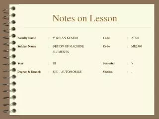
Topic 2: Instruction Set Architecture Design Adapted from Prof. Jerry Breecher’s Notes + my CS21Q Notes (http://babbage.clarku.edu/~jbreecher/arch/arch.html) EE37E 2005
Introduction 7.1 Introduction 7.2 Classifying Instruction Set Architectures 7.3 Memory Addressing 7.4 Operations in the Instruction Set 7.5 Type and Size of Operands 7.6 Encoding and Instruction Set 7.7 The Role of Compilers 7.8 The MIPS Architecture and Bonus 7.9. Endianess EE37E 2005
software instruction set hardware Introduction The Instruction Set Architecture is that portion of the machine visible to the assembly level programmer or to the compiler writer. Questions: - What are the advantages and disadvantages of various instruction set alternatives? - How do languages and compilers affect ISA? EE37E 2005
Classifying Instruction Set Architectures Classifications can be by: • Stack/accumulator/register • Number of memory operands. • Number of total operands. EE37E 2005
Basic ISA Classes Instruction Set Architectures Accumulator: 1 address add A acc ¬ acc + mem[A] 1+x address addx A acc ¬ acc + mem[A + x] Stack: 0 address add tos ¬ tos + next General Purpose Register: 2 address add A B EA(A) ¬ EA(A) + EA(B) 3 address add A B C EA(A) ¬ EA(B) + EA(C) Load/Store: 0 Memory load R1, Mem1 load R2, Mem2 add R1, R2 1 Memory add R1, Mem2 ALU Instructions can have two or three operands. ALU Instructions can have 0, 1, 2, 3 operands. Shown here are cases of 0 and 1. EE37E 2005
Basic ISA Classes Instruction Set Architectures The results of different address classes is easiest to see with the examples here, all of which implement the sequences for C = A + B. Registers are the class that won out. The more registers on the CPU, the better. EE37E 2005
Intel 80x86 Integer Registers Instruction Set Architectures EE37E 2005
Memory Addressing Sections Include: Interpreting Memory Addresses Addressing Modes Displacement Address Mode Immediate Address Mode EE37E 2005
Interpreting Memory Addresses Memory Addressing What object is accessed as a function of the address and length? Objects have byte addresses – an address refers to the number of bytes counted from the beginning of memory. Little Endian – puts the byte whose address is xx00 at the least significant position in the word. Big Endian – puts the byte whose address is xx00 at the most significant position in the word. Alignment – data must be aligned on a boundary equal to its size. Misalignment typically results in an alignment fault that must be handled by the Operating System. EE37E 2005
Addressing Modes Memory Addressing This table shows the most common modes. A more complete set is in Figure 2.6 EE37E 2005
Displacement Addressing Mode Memory Addressing How big should the displacement be? For addresses that do fit in displacement size: Add R4, 10000 (R0) For addresses that don’t fit in displacement size, the compiler must do the following: Load R1, address Add R4, 0 (R1) Depends on typical displaces as to how big this should be. On both IA32 and DLX, the space allocated is 16 bits. EE37E 2005
Immediate Address Mode Memory Addressing Used where we want to get to a numerical value in an instruction. At high level: a = b + 3; if ( a > 17 ) goto Addr At Assembler level: Load R2, 3 Add R0, R1, R2 Load R2, 17 CMPBGT R1, R2 Load R1, Address Jump (R1) So how would you get a 32 bit value into a register? EE37E 2005
Operations In The Instruction Set Sections Include: Detailed information about types of instructions. Instructions for Control Flow (conditional branches, jumps) EE37E 2005
Operator Types Operations In The Instruction Set Arithmetic and logical and, add Data transfer move, load Control branch, jump, call System system call, traps Floating point add, mul, div, sqrt Decimal add, convert String move, compare Multimedia - 2D, 3D? e.g., Intel MMX and Sun VIS EE37E 2005
Control Instructions Operations In The Instruction Set Conditional branches are 20% of all instructions!! Control Instructions Issues: • taken or not • where is the target • link return address • save or restore Instructions that change the PC: • (conditional) branches, (unconditional) jumps • function calls, function returns • system calls, system returns EE37E 2005
Type And Size of Operands The type of the operand is usually encoded in the Opcode – a LDW implies loading of a word. Common sizes are: Character (1 byte) Half word (16 bits) Word (32 bits) Single Precision Floating Point (1 Word) Double Precision Floating Point (2 Words) Integers are two’s complement binary. Floating point is IEEE 754. Some languages (like COBOL) use packed decimal. EE37E 2005
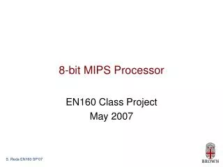
The MIPS Architecture MIPS is very RISC oriented. EE37E 2005
The MIPS Architecture • Addressing Modes • Immediate • Displacement • (Register Mode used only for ALU) There’s MIPS – 32 that we learned in CS140 32bit byte addresses aligned Load/store only displacement addressing Standard datatypes 3 fixed length formats 32 32bit GPRs (r0 = 0) 16 64bit (32 32bit) FPRs FP status register No Condition Codes MIPS Characteristics • Data transfer • load/store word, load/store byte/halfword signed? • load/store FP single/double • moves between GPRs and FPRs • ALU • add/subtract signed? immediate? • multiply/divide signed? • and,or,xor immediate?, shifts: ll, rl, ra immediate? • sets immediate? There’s MIPS – 64 – the current arch. Standard datatypes 4 fixed length formats (8,16,32,64) 32 64bit GPRs (r0 = 0) 64 64bit FPRs EE37E 2005
The MIPS Architecture MIPS Characteristics • Control • branches == 0, <> 0 • conditional branch testing FP bit • jump, jump register • jump & link, jump & link register • trap, returnfromexception • Floating Point • add/sub/mul/div • single/double • fp converts, fp set EE37E 2005
Register-Register 6 5 11 10 31 26 25 21 20 16 15 0 Op Rs1 Rs2 Rd Opx Register-Immediate 31 26 25 21 20 16 15 0 immediate Op Rs1 Rd Branch 31 26 25 21 20 16 15 0 immediate Op Rs1 Rs2/Opx Jump / Call 31 26 25 0 target Op The MIPS Architecture The MIPS Encoding EE37E 2005
Byte Ordering • How should bytes within multi-byte word be ordered in memory? • Conventions • Sun’s, Mac’s are “Big Endian” machines • Least significant byte has highest address • Alphas, PC’s are “Little Endian” machines • Least significant byte has lowest address EE37E 2005
0x100 0x101 0x102 0x103 01 23 45 67 0x100 0x101 0x102 0x103 67 45 23 01 Byte Ordering Example • Big Endian • Least significant byte has highest address • Little Endian • Least significant byte has lowest address • Example • Variable x has 4-byte representation 0x01234567 • Address given by &x is 0x100 Big Endian 01 23 45 67 Little Endian 67 45 23 01 EE37E 2005