Evolving Adaptive Filters and Programmable Circuits for Enhanced Electronics Performance
This document explores advanced applications in electronics, focusing on programmable compensation mechanisms for analog circuits, clock skew compensation in digital systems, and automated design through genetic programming. It discusses the evolution of adaptive filters for real-time responses to mission changes, the challenges of operating in extreme temperatures, and the integration of fault-tolerance strategies. The research highlights the innovative use of reconfigurable hardware that adapts to environmental changes, demonstrating capabilities through both simulation and hardware experiments.

Evolving Adaptive Filters and Programmable Circuits for Enhanced Electronics Performance
E N D
Presentation Transcript
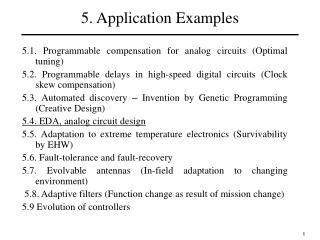
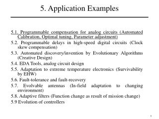
5. Application Examples 5.1. Programmable compensation for analog circuits (Optimal tuning) 5.2. Programmable delays in high-speed digital circuits (Clock skew compensation) 5.3. Automated discovery – Invention by Genetic Programming (Creative Design) 5.4. EDA Tools, analog circuit design 5.5. Adaptation to extreme temperature electronics (Survivability by EHW) 5.6. Fault-tolerance and fault-recovery 5.7. Evolvable antennas (In-field adaptation to changing environment) 5.8. Adaptive filters (Function change as result of mission change) 5.9 Evolution of controllers 1
Evolution of Filters • Binary representation used both in simulation and HW experiments: • Simulation experiments using SPICE models of the first FPTA chip; • Hardware experiments using FPTA-2 chip; • Circuits evaluated in the frequency domain: • Simulation: small signal analysis in SPICE; • Real hardware: FFT of the circuit transient response. 2
Filter Evolution in Simulation Cell Topology: Small capacitors (0.1nF) placed between drain and gate to explore Miller effect Each cell has 8 fixed MOS transistors, 24 switches, 4 capacitors 3
Filter Evolution in simulation N Fitness Evaluation Function → wi |Oi – Ti| i=0 • where: • N is the number of samples in the frequency domain; • Oi is the circuit output in the frequency domain; • Ti is the target output in the frequency domain • (low-pass, band-pass, etc); • wi are weights whose values should be carefully set. • Weight values are usually larger in the passing band • comparing to the stop band. 4
Filter Evolution in Simulation Input Output Roll-off Of 40 dB/decade Roll-off of -20 dB/decade Roll-off of 35 dB/decade An example of a band-pass filter evolved on the 4 FPTA cells • Wide Band Filter: Gain of 10 dB between 100kHz and 1MHz with roll-off of 40 dB/decade before 100kHz and -20 dB/decade after 1Mhz. • Narrow Band Filter: Gain of 2 dB between 1kHz and 10kHz with roll-off of -35dB/decade. Stop band below 100Hz and above 100kHz. 5
Filter Evolution in Hardware sin(2f1t) In(t) = + sin(2f2t) Reconfigurable HW FPTA-2 FFT Computation in the DSP Output f1: Filter Cut-off frequency f2: Stop-band starting frequency • Reconfigurable device: FPTA-2 • Experiments performed on SABLES platform: about 5 minutes evolution time; Fitness function maximizes output FFT component at f1 and minimizes the one at f2. 6
Filter Evolution in Hardware Evolved Low-Pass Filter Evolved High-Pass Filter Input Input Output Output • Low-pass (f1/2 = 1kHz/10kHz) and high-pass filters (f2/1 = 1kHz/10kHz); • Use of 10 cells of the FPTA-2 chip; 7
Adaptive filters • Genetic Algorithm self-tunes response of the filter (Simulation experiment); • Adaptation based on filter inputs: Hardware experiment ; • Goal: Function change as result of mission change. 8
Reconfigurable “Adaptive” Band-Pass 5kHz, 25kHz Evolved in Simulation Filter 1 Gain = 11.4dB Roll-off: 34dB/dec, -30dB/dec 1 2 Filter 2 Gain = 9dB Roll-off: 43dB/dec, -70dB/dec GA changes circuit topology through reconfiguration to respond to a new functional (frequency response) requirement 9
Evolvable Adaptive Filter in Hardware • Demonstrate that FPTA2 can synthesize low and high pass filters without external capacitors: same piece of hardware can be reconfigured to realize low-pass and high-pass frequency responses • Evolution of adaptive functionality: Filter reacts to change in the input signal • Evolution of filters that amplify strongest input signal and attenuate weakest signal (“noise”); • Circuit ‘does not know’ frequency spectrum at the input; • Adaptation through reconfiguration: new circuit evolved to cope with changes at the input signal. 10
Evolvable Adaptive Filter in Hardware • Input signal: • Sum of two signals: 10kHz and 25kHz tones • Strong (signal) and Weak (noise) tones not known a priori • FPTA cells: • Explore resistance of switches: partly opened/closed switches; • Four cells constrained to be inverters; • Evolved connections among cells • Fitness Function: • Evaluate the FFT of output • Amplify strong signal, attenuate weak signal • Genetic Algorithm: • 400 individuals/200 generations; • Time on SABLES: 5 min 11
Adaptive Filter Results Signal/Noise = 10.8dB Input Input Signal/Noise = 4.1dB Output Signal/Noise = 18.5dB Output Signal/Noise = 16.9dB • Filter characteristic: • 10kHz : -2.86dB attenuation • 20kHz : -15.8dB attenuation • Filter characteristic: • 10kHz : -12.5dB attenuation • 20kHz : -4.8dB attenuation 12