Download
1 / 33
330 likes | 460 Views
Centrifuge Model Study of Impact on Existing Undercrossing Induced by Deep Excavation. Z.W.Ning, X.Y.Xie, F.Z.Liu, X.R.Liu. Dept. of Geotechnical Engineering, Tongji University. The 5th China-Japan Joint Seminar for the Graduate Students in Civil Engineering, Nov. 7th-10th, 2008. Contents.

E N D
Centrifuge Model Study of Impact on Existing Undercrossing Induced by Deep Excavation Z.W.Ning, X.Y.Xie, F.Z.Liu, X.R.Liu Dept. of Geotechnical Engineering, Tongji University The 5th China-Japan Joint Seminar for the Graduate Students in Civil Engineering, Nov. 7th-10th, 2008
Contents • Introduction • Centrifuge Test Facility • Test Set-up & Procedures • Result Analysis • Conclusions
Contents • Introduction • Centrifuge Test Facility • Test Set-up & Procedures • Result Analysis • Conclusions
Shanghai Rail Transit Planning Shanghai Rail Transit Planning Yuanshen Road Ventilation Shaft Line 9 研究背景与主要研究内容
Project Introduction Excavation 20m 25m Undercrossing Excavation Undercrossing Excavation: 35m in depth Undercrossing: 34m in width, 6 lanes. Distance between the excavation and the undercrossing: 3m.
Project Introduction 10 m 10 m 40m diaphragm wall Length: 59m Thickness: 1.2m 9 levels of inner struts Barrier Piles-wall Length: 40m Width: 40m Diameter of piles: 850mm Piles-wall In order to protect the undercrossing, a barrier piles-wall made up ofφ850mm mixing piles was constructed between the excavation and the undercrossing. The depth of the piles-wall is 40m and extends 10m laterallyfrom the boundary of the excavation on each side.
Principle of Centrifuge Modeling Centrifuge modeling is a useful tool to study the geotechnical problems because of its ability to reproduce the same stress level in a small-scale model.
Contents • Introduction • Centrifuge Test Facility • Test Set-up & Procedures • Result Analysis • Conclusions
Excavation Simulation Approaches on Centrifuge Simulation Approaches Conduct by on-board robot or special device in-flight Remove soil and construct struts by hand when stopping the centrifuge Effective but Complicate Weakness:It does not reproduce the real stress path of soil correctly. Drain off heavy liquid in-flight instead of soil excavation Weakness:the horizontal and vertical stress of soil can not be correctly simulated at the same time.
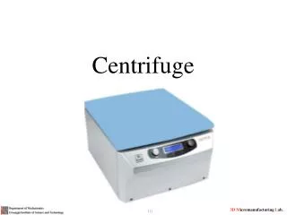
TLJ-150 Centrifuge in Tongji University Centrifuge Control Room Capacity: 150 g-tons Maximum g: 200 g Effective r: 3m In-flight Robot Strong Box
Excavation and Struts Installation Simulation Device In present study, a new device to simulate the installation of multi-level inner struts in-flight was developed and the draining-fluid method was used at the same time. All the tests stated here were carried out at Tongji Centrifuge Laboratory in 100g acceleration filed. The operations of the device can be conducted through a uniform control platform in the control room.
Demonstration of Simulation Concept Locked Locked Locked All the struts can move freely in horizontal direction at the beginning. When the surface of the replacing liquid fell beneath struts at a certain level, the position of those struts would be fixed by activating the hydraulic-control locks on them.
Details of Simulation Device Steel strut Hydraulic-control valve Hydraulic-control lock The strut is made of steel bar with a load cell inside to measure its inner force. The hydraulic-control lock is installed at the end of each strut to lock or free it. A hydraulic-control valve is used to accurately drain the liquid step by step to any level according to the real excavation procedures.
Contents • Introduction • Centrifuge Test Facility • Test Set-up & Procedures • Result Analysis • Conclusions
Simplifications & Assumptions Strong Box Steel Plate • Only half part of the prototype was modelled due to the symmetric layout of the real project. • The ground profile was simplified into 3 layers: Clay, Silt, Fine Sand (top-down) • The struts were reduced into 5 rows by two columns. Due to the limit free space in the strongbox. To make sure an equivalent lateral rigidity of the whole retaining structure to the prototype, compensation were made both in the thickness of the diaphragm wall and the radius of the struts.
Tests Design In present study, four 1:100 scale centrifuge model tests were performed in a strongbox with internal dimension of: 900mm×700mm×700mm. Test1, Test2 and Test3 differed in parameters of barrier piles-wall. Test 4 was an extra test with no excavation.
Instrumentation 6 LVDTs to measure the settlement of the undercrossing in two directions. 10 load-cells to measure the struts’ stress. 5 eddy current sensors to measure the displacements of the struts at 5 different levels(-2m, -9m, -16m, -23m ,-30m).
Undercrossing Undercrossing Barrier Piles-wall Barrier Piles-wall Diaphragm wall Diaphragm wall Model &Instrumentation Arrangement Model Scale:1:100 Plan view Cross-section 1-1
Model Preparation Clay Silt Fine Sand The ground model consisted of three layers : Clay, Silt, and Find Sand. The clay and silt were saturated at first and then were consolidated in the centrifuge under 100g for 2-3 hours until at least 90% degree of consolidation was achieved. The Na2O.3SiO2 solution with a density of 1.36g/ml was employed in these tests providing a lateral pressure close to the soil.
Model Preparation Diaphragm Wall Undercrossing Aluminum plates with various thicknesses were used to model the diaphragm wall, undercrossing structure and the barrier piles-wall according to the flexural stiffness of the prototype.
Model Preparation 1 2 3 4
Contents • Introduction • Centrifuge Test Facility • Test Set-up & Procedures • Result Analysis • Conclusions
Acceleration Time-history Curve 100g The duration for each test keeping on 100g was around 20 minutes corresponding to approximately 5-month excavation period in real project.
Undercrossing settlement time-history curves The typical settlement time-history curves of the undercrossing observed in Test 1
Settlement of test 1 and field monitoring in cross-section 1-1 1 1
Settlement of test 1, test2 and test3 in cross-section 1-1 1 1
Settlement of test 1 and field monitoring in cross-section 2-2 2 2 Range of Excavation
Settlement of test 1, test2 and test3 in cross-section 2-2 2 2 Range of Excavation
Contents • Introduction • Centrifuge Test Facility • Test Set-up & Procedures • Result Analysis • Conclusions
Conclusions • The newly developed device was proved to be workable under 100g high acceleration field. It provide an effective way to accurately simulate the excavation and struts installation procedures in-flight in centrifuge modeling test. • The impact of the excavation on adjacent undercrossing was unneglectable with an impact range of about 3 times the width of the excavation along the direction parallel to the undercrossing. The impact weakened rapidly as the distance from the excavation increases. • Barrier piles-wall was effective in protecting the undercrossing. The longer the piles-wall, the less settlement occurred. However, there was no significant difference of undercrossing settlement between tests with and without piles-wall beyond the excavation range. It is suggested that the width of piles-wall could be controlled within 2 times the width of the excavation.
Dicussions • Because liquid can not simulate the horizontal and vertical stress of soil at the same time. We are trying to find the relationship between the liquid density and the test results by numerical simulation in our further research. • The interface between model and strongbox should be carefully treated. In our tests, the displacement of soil model near the boundary was affected by the interface friction. • The Na2O.3SiO2 solution we chose to replace the soil cause a larger bottom heave than the real case due to its relative low pressure in vertical direction. Thus, the observed settlement in our tests were larger than the real case as well.
Thank You ありがとうございます The 5th China-Japan Joint Seminar for the Graduate Students in Civil Engineering, Nov. 7th-10th, 2008