Download
1 / 32
320 likes | 438 Views
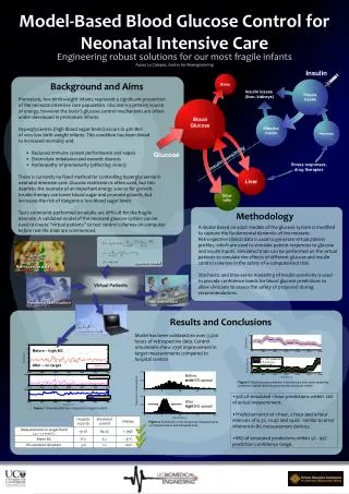
Explore the fundamentals of real-time systems and adaptive cruise control, including driver and functional models, timing constraints, task mapping, and more. Learn about the properties, types, and dimensions of real-time systems, with a focus on safety, liveness, and timeliness. Understand the significance of timing constraints and the role of environmental characteristics. Delve into adaptive cruise control functionality, human driver models, and car-following models for enhanced vehicle safety and efficiency.

E N D
Roadmap • Introduction to RTS • Problem Definition / Motivation • Adaptive Cruise Control (ACC) • Driver Models • Functional Model & Task Model • Extensions to Functional Model • Conclusion & Future Work • References
F2 FunctionalDesign F5 F1 F4 F3 (F2) ArchitecturalDesign Thread (F5) HW1 HW2 HW3 HW4 (F3) (F4) RTOS/Drivers Hardware Interface Functional Design & Mapping Source:Ian Phillips, ARM VSIA 2001
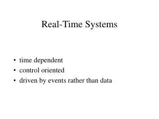
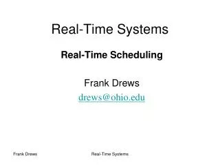
computer world e.g., PC average response for user Interactive occasionally longer reaction: user annoyed computer controls speed of user “computer time” real world Industrial system, airplane environment has own speed reaction too slow: deadline miss reaction: damage, pot. loss of human life computer must follow speed of environment “real-time” What is “real” about real-time?
I/O - data event time Real-time computing system action I/O - data Real-Time Systems A real-time system is a system that reacts to events in the environment by performing predefined actions within specified time intervals.
Real-Time Systems: Properties of Interest • Safety: Nothing bad will happen. • Liveness: Something good will happen. • Timeliness: Things will happen on time - by their deadlines, periodically, ...
Types of RT Systems Dimensions along which real-time activities can be categorized: • how tight are the deadlines? --deadlines are tight when laxity (deadline -- computation time) is small. • how strict are the deadlines? what is the value of executing an activity after its deadline? • what are the characteristics of environment? how static or dynamic must the system be?
value hard soft time + deadline (dl) Hard, soft, firm • Hard -- result useless or dangerousif deadline exceeded Ex: Aircraft, Chemical Plant • Soft -- result of some - lower value if deadline exceeded • Ex: Multimedia, Interactive video games - • Firm -- If value drops to zero at deadline
Timing Constraints Real-time means to be in time --- how do we know something is “in time”?how do we express that? • Timing constraintsare used to specify temporalcorrectnesse.g., “finish assignment by 2pm”, “be at station before train departs”. • A system is said to be (temporally) feasible, if it meets all specified timing constraints. • Timing constraints do not come out of thin air:design process identifies events, derives models, and finally specifies timing constraints
Overall Picture Physical properties of environment Model-design Timing constraints Analysis, Testing Run-time dispatching (In field use) Functional Temporal
Timing Properties • Periodic • activity occurs repeatedly • e.g., to monitor environment values, temperature, etc. • Aperiodic • can occur any time • no arrival pattern given • Sporadic • can occur any time, but • minimum time between arrivals mint time
Who initiates (triggers) actions? Example: Chemical process • controlled so that temperature stays below danger level • warning is triggered before danger point …… so that cooling can still occur Two possibilities: • action whenever temp raises above warn-- event triggered • look every int time intervals; action when temp if measures above warn -- time triggered
Other Issues to worry about • Meet requirements -- some activities may run only: • after others have completed - precedence constraints • while others are not running - mutual exclusion • within certain times - temporal constraints • Scheduling • planning of activities, such that required timing is kept • Allocation • where should a task execute?
Motivation (Cont…) • Partitioning of system into TT and ET domains • Process Mapping • Optimization of parameters corresponding to communication protocol. • Sequence and Slots of TDMA (TTC) • Priorities of Messages (ETC) • Schedulability
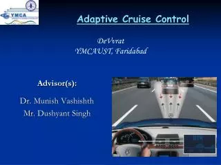
Adaptive Cruise Control • Adaptive Cruise Control: • automatically adjusts vehicle speed to maintain a driver-selected safe distance from the vehicle ahead in the same lane. • It then returns to the set speed when traffic clears. • Requirements: • The speed should be kept close to the SET speed, if there is no vehicle ahead. • Timegap should be maintained at x sec. • Manual intervention, UI, etc…
Functions Identified • Computing Current speed of our vehicle • Leading Vehicle related Task • Controlling Speed of our Vehicle • Controlling the Throttle • Controlling the Brake • Detecting Manual Intervention • UI to the Driver • Periodicity of Tasks • Hard, Firm; Periodic, Aperiodic…
Human Driver Model • Stimulus-Reaction Model Structure of Human Driver in Car-Following
Car Following Models • Linear Follow-the-Leader Model • Stimulus: Velocity Difference b/w Leader and Follower • Reaction: Acceleration command to vehicle • Look-Ahead-Model • Driver observes the behavior of three vehicles ahead of him. • Stimulus: Majority direction of Acceleration • Reaction: Acceleration command using switching logic • Others…
Simple Car Following Model vl Velocity of Leader vf Velocity of Follower rl Retardation of Leader rf Retardation of Follower tr Short Reaction Time
Acceleration profile of vehicle Dmin = Di – Di-1 Di = D1i + D2i + D3i
(air drag, grade, friction etc) Disturbances (accelerator pedal (throttle) position, brake pedal position) Physical Process Actuator Noise (vehicle speed) Control I/P Actual output Desired Control I/P Actuators (desired vehicle speed) Sensed O/P Adaptive Cruise Cont. Reference Input Sensor Noise Sensors (wheel speed sensor) ACC System Design Src: Prof. Shashikant's Control System Lec-1 in DEP Mode
1/M 1/Rw Disturbances G E Physical Process Control I/P Actual Output Process Model Src: Prof. Shashikant's Control System Lec-1 in DEP Mode
Pictorial View Sensors Actuators Friction Estimator Schematic Picture of Control Algorithm and its Environment Throttle System Speed Sensor Control Algorithm Radar System ABS Roadside Signals as SPEED Module The structure of Control Algorithm Min-value Control Signal to the Actuators DISTANCE Module ad
Flow Chart (cont…)
Wheel S a Throttle A IR S b d c Brake A Speed Set g e Throttle S f Brake S Precedence Graph showing communication relation Curr_Thr Pos Curr_Br Pos
Extensions to Functional Model under consideration • Adaptive to • Driver Reaction Time • Roadside Signals • Friction b/w road and tyre (ABS) • Relative positioning in the lane
Future Work • Partitioning tasks as TT and/or ET and as Soft, Hard or Firm. • Writing Algorithm • Allocation of Tasks • Schedulability • One or two similar application if time permits