Download
1 / 60
600 likes | 616 Views
This research explores the integration of a teleoperated and autonomous system using the Sensor Brick Concept, allowing for the gradual transition from teleoperation to autonomy without major hardware changes. The main contributions include the mobility brick paradigm, which enables multiple sensor and mobility bricks to communicate and complete various missions.

E N D
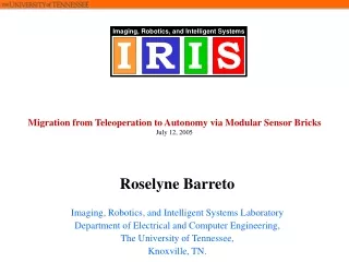
Migration from Teleoperation to Autonomy via Modular Sensor and Mobility Bricks ROSELYNE BARRETO April 28, 2006 Imaging, Robotics, and Intelligent Systems Laboratory Department of Electrical and Computer Engineering, The University of Tennessee, Knoxville, TN.
Outline • Introduction • Research Contributions • Motivation • Applications • Related Works • Migration to Autonomy • Results and Analysis • Conclusion • Future Work
Introduction • Robotics: Promising but challenging research area. • Full autonomy: Research still limited. • Removing the operator is not an option. • Studies show that there is usually a trade off when going from teleoperation to autonomy. • The objective of this thesis is to integrate both a teleoperated and autonomous system into one using the Sensor Brick Concept. ANDIBot
Introduction • Teleoperated robots are opposed to autonomous robots in that they absolutely require human input. • Autonomous systems use sensors to “feel” their environment, therefore going from teleoperation to autonomy imply hardware changes. • Most autonomous systems focus on navigation or simple assembly tasks, hence acquiring autonomy sometime implies being task specific. • This research emphasizes two main points: the transition does not involve major hardware changes and the acquired autonomy is not limited to a few basic sensors or a few applications.
Research Contributions • The goal of this work is to gradually move from the original teleoperation, to an enhanced computer interfaced–teleoperation to an autonomous system. • The contributions of this research are: • The Reverse Engineering of the ANDROS Mark VA, • the Upgrade of the original system to acomputer-interfaced teleoperated system and the, • the mobility brick paradigm and, • the additionof autonomouscapability.
Teleoperation Original OCU Computer Interface Reverse Engineering Reverse Engineer Computer Integration Sensor Bricks Original OCU Autonomy Mobility Bricks Migration from Teleoperation to Autonomy Robot Research Contributions
Research Contributions • The main contribution of this thesis reside in the mobility brick paradigm. This paradigm is a shift from the proprietary commercial models that exist today. The mobility platform are now controllable by OCU located in different locations in the Sensor Brick System. • This works fits in the ultimate goal of having several sensor and mobility bricks communicating together to complete different missions.
Research Contributions Mobility Brick Paradigm in Sensor Brick System
Motivation The three main motivations for this work are: • Keeping the operator in the loop for safety reasons for example in Explosive Ordnance Disposal operations. • Adding Modularity and Flexibility: Being able to add sensors without major hardware changes to the original robust commercial robot. • Using these modular sensors to acquire some autonomy without being restricted to a specific application.
Applications Example of applications for this system are: • DOE: chemical safety, nuclear safety and hazardous waste transport. NNSA facilities security (Physical PerimeterSecurity) • Scouting missions for the Weapons of Mass Destruction Civil Support Team WMD CST for example • Vehicle Inspection illustrate points such as reachability and complete scrutiny of the vehicle (different sensors reveal additional complementary information) • ARC: autonomous data collectionand fusion for simulation
Images from orau.gov Applications • DOE/NNSA: • Chemical and nuclear safety • Hazardous waste transport • Physical Perimeter Security • Emergency Response • Gate Check Point Inspections • Personal Evacuation Emergency Response Physical Perimeter Security
Applications Image from globalsecurity.org WMD CST’s Scouting Needs The WMD CST provide unique expertise and capabilities to assist in responding to chemical, biological, radiological and nuclear incidents. Scouting Missions
Applications • Vehicle Inspection: • Some areas are hard to reach for human operators. • Different sensors detect complementary information. • Unmanned systems provide this information while keeping the operator out of danger. Automated Under-Vehicle Inspection
Related Work • The Related Work section of this thesis focuses on achieving autonomy. • Autonomous robots are aimed to be physical entities that can accomplish tasks without human intervention. • This section presents the principle, the challenges negotiated, the different levels involved and system analysis in going from teleoperation to autonomy. • The research on autonomy can be subdivided into autonomous mobile robots and task-oriented systems.
Related Work • Task-oriented autonomy include: • Programming by demonstration, which allows the programmer to teach a task to a robot simply by wearing special equipment. • Behavior-based systems, which are based on recognizing objects and answering to trigger-base commands. • Methods for autonomous mobile robots include: • Visual and non-visual homing which focus on navigation. • Teleautonomy [1], which helps the robot balance itself and move steadily while the operator focuses on a task. [1] Conway, 1990
Related Work • In recent attempts to simplify this process, The Office of Secretary of Defense Joint Robotic Program has developed a new architecture: Joint Architecture for Unmanned Systems. • JAUS increases the modularity and flexibility of robotic systems by providing a common messaging protocol between their components • This idea allows the interoperability between different systems. • As parts become defective or outdated, the whole system is not entirely affected.
Related Work Two important points stand out of the related work section: • There is usually a trade off between teleoperation and autonomy. Studies in this area confirm that automation is a time consuming and complex engineering exercise. • When creating an autonomous system, keys words are: modularity, flexibility and interoperability.
Communication Sensor Pre-processing Power Related Work • The IRIS lab Sensor Brick System has previously been defined from the Sensor Brick Concept [2]: • This work uses this concept to migrate from teleoperation to autonomy. Sensor Brick [2] Wilson, 2005
Migration to Autonomy • Examples of teleoperated systems that are targeted in this work. Basic Teleoperation
Advantages: The emphasis in such system is not on having a sophisticated robot but rather a reliable elementary system. These robust systems include features such as climbing stairs, surviving 2m drops onto concrete ground and more. When operated by experts, they are very efficient and keep operators out of harm’s way. Limitations: Untrained operators cannot properly maneuver these robots. They do not usually include sophisticated sensors; a few basic sensors such as a surveillance camera may relay information to the OCU. Special sensors have to be ordered and custom made for different applications. Different commercial robots are not interoperable. Migration to Autonomy
Migration to Autonomy – Part 1 • This process starts with the original ANDROS Mark VA version. Remotec ANDROS Mark VA
Migration to Autonomy – Part 1 • The first step in the migration is moving from a proprietary system to an open programmable Operator Control Unit (OCU). • This process involves: • Reverse Engineering the original OCU • To analyze the native controller, Kermit 95 (K95) an extensive file transfer protocol allows capturing the output signals. • Storing the appropriate commands into a GUI • Then a C++ program sends those same signals to the robot.
Migration to Autonomy – Part 1 • In the first phase of the reverse engineering process the controller is linked to a PC using an RS-232 line and K95 Graphical User Interface. Kermit Set Up
Migration to Autonomy – Part 1 • A text file captures the K95 sessions and allows a clear analysis of the strings. Kermit Session
Fire weapon Laser 0A000C2000908D80C0Æññ Arm Speed Vehicle Speed Light Migration to Autonomy – Part 1 • Characters control the body and drive motions as well as the different settings. The last character before the separators is an ASCII Check Sum. String Command
Migration to Autonomy – Part 1 • First assumption: check sum is hexadecimal. • First solution: Create a database of 2*2*2*22 strings. • Once the logic of the string is understood, the programmer can individually change characters and simply generate the correct check sum.
ANDROS F6A • The same reverse engineering process was conducted on a newer version of the ANDROS. • From a programming point of view the only differences between the two systems are the length and speed of the strings. The logic and functionality behind the characters is still the same. • From a hardware stand point however there is a more unique relationship between the OCU and the robot. • In order to get the same results the PC has to be able to closely match the original OCU.
ANDROS F6A • The waveform coming from the new OCU cannot be generated directly from a regular PC.
Migration to Autonomy – Part 1 • A C++ program finally generates and sends the strings to the robot at 1200 baud rate. Original Mechanical Controller New Control GUI
Migration to Autonomy – Part 2 • Migrating to an autonomous system implies giving intelligence to the robot. • To avoid giving all decision making to the unmanned system, a main computer and the on-board computer still need to collaborate. • Consequently, the next step was to subdivide the system into a main OCU and a mobility brick. • The same concept is used in modular robotic architectures, specifically in JAUS Primitive Driver. • Each subsystem is an independent unit.
Communication Communication Mobility Sensor Pre-processing Pre-processing Power Power Migration to Autonomy – Part 2 • The mobility Brick is defined based on the Sensor Brick Concept. Sensor and Mobility Brick
802.11 RS 232 802.11 RS 232 Communi- cation Pre- processing Mobility Main Control Power Migration to Autonomy – Part 2 • The 802.11g wireless communication protocol replaces the RS-232 hardware connection. Conversion into a Mobility Brick
Migration to Autonomy – Part 2 • The brick can be operated on its own by remote login or can be used in the server-client configuration. • The basic version of the mobility brick does not include any particular sensor. Mobility Brick V 1
Migration to Autonomy – Part 3 • Finally the migration to autonomy integrates the mobility brick and the sensor brick to create an autonomous system. • The operator can launch and supervise an autonomous operation but also interrupt it at any point. • In this particular application the robot uses the range sensor brick to autonomously follow a wall. • This application falls under the Physical Perimeter Security Concept. Replacing the soldier by a Robot
Sensor Brick Sensor to Processor Processor Processor to Processor Shared Processor Processor Mobility Brick Processor to Mobility Migration to Autonomy – Part 3 • Configuration of mobility and sensor brick; for practical reason the system uses a shared processor. Mobility and Sensor Brick Configuration
Migration to Autonomy – Part 3 • The Autonomous Navigation and Directed Imaging Robot (ANDIBot) consists of the mobility brick and the range sensor. ANDIBot’s Hardware Implementation
dwall dfront 2*Do 2*Do cos(θ) = sin(θ) = Wall dwall y dview θ R x Robot Robot front view Do Migration to Autonomy – Part 3 • The mobility/sensor brick set up: => θ= 45 ,
Migration to Autonomy – Part 3 • The mobility/sensor brick set up: Avoiding Obstruction from Arm Forward Direction Mobility and Sensor Brick Configuration
Migration to Autonomy – Part 3 • The algorithm: y d Right End Y Wall Left End Y R x Robot θ D Algorithm Basic Logic
Algorithm Flowchart Migration to Autonomy – Part 3
Analysis Experimental Set Up
Analysis • The goal of the analysis is to provide the programmer with pertinent information regarding the autonomous functionality of the robot. • The first part provides information about the string commands and the second emphasizes the characteristics of the wall following algorithm. • To characterize the strings, the robot’s performance is studied on different grounds and at different battery levels.
Mark VA Repair • During the course of this analysis the ANDROS broke down; the defective part was identified and replaced.
Analysis – Part 1 Flat Concrete Carpet Experiments for Forward and Backward Motions
Analysis – Part 1 Flat Concrete Carpet Experiments for Turning Motions
Analysis – Part 1 • The raw measurements show the consistency of the data.
Analysis – Part 1 • The fluctuation of the data around the average confirms the previous observation.
Analysis – Part 1 • The relationship between the covered distance and the number of strings is almost linear.
Analysis – Part 1 • The performance of the robot decreases on floors with higher friction.
Analysis – Part 1 • The effect of a higher friction floor is estimated to be approximately 13%.