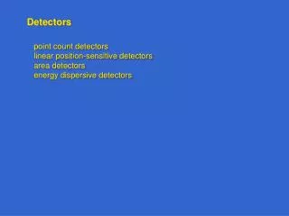
Detectors
Detectors. RIT Course Number 1051-465 Lecture: Diodes, Transistors, FETs. Aims for this lecture. To describe the principles behind important electrical components for detectors To provide working knowledge of these components To give examples of the components used in detector applications.

Detectors
E N D
Presentation Transcript
Detectors RIT Course Number 1051-465 Lecture: Diodes, Transistors, FETs
Aims for this lecture • To describe the principles behind important electrical components for detectors • To provide working knowledge of these components • To give examples of the components used in detector applications
Lecture Outline • Theory and operation of electrical components • diode • photodiode • light emitting diode (LED) • transistor • field-effect transistor (FET) • junction field-effect transistor (JFET) • metal-oxide field-effect transistor (MOSFET) • Detector applications • pixel photodiode • source follower • amplifier
Definition of a Diode • A diode is an electronic component that • has two terminals, • limits current to one direction, and • has nonlinear (non-Ohmic) behavior. • Diodes have an anode and a cathode. • Positive current normally flows from the anode to the cathode. • Diodes are useful for protecting circuitry from harmful voltage or current. • Diodes are a basic building block of the charge-collecting element in many detectors.
Review of pn Junction • Most diodes are based on the pn junction architecture. • Initially, electrons move from n to p-side and holes from p to n-side. • Depletion region is formed at interface - ion cores remain. • Results in a built-in electric field (103 to 105 V/cm). • Fermi energy levels are equal across pn junction. Positive charge has higher potential energy on n-type side, but it cannot move to the p-type side if it is locked in the valence band of the crystal lattice.
p n “reverse” bias “forward” bias Biasing a Diode • Construct pn junction (open circles are holes). • Make contact and depletion region is formed. • Apply “forward” or “reverse” bias voltage.
Diode IV Curve • Diode behaves linearly (ohmic) near zero voltage. • Reverse breakdown occurs when applied reverse voltage produces a strong enough potential across the depletion region so that the energy of the valence electrons in the p-type material exceeds the energy of the conduction band in the n-type material. This leads to stripping of electrons and damage.
Definition of a Photodiode • A photodiode is a diode that converts photons into voltage or current. • This conversion happens when photons of sufficiently high energy promote photogenerated charge into the conduction band of the semiconductor. • The photogenerated charge migrates to the depletion region where it recombines with ions.
Avalanche Photodiode • Photon absorbed in intrinsic layer. • Photogenerated electrons drift to pn+ junction where they are accelerated through high field, producing more electrons. • Benefit: one photon gives large signal.
Definition of a Light Emitting Diode (LED) • A Light Emitting Diode converts electrical current into light. • LEDs are based on pn junctions under forward bias. • The wavelength of emitted light is fixed for a material and depends on the energy gap between the conduction band and the hole energy level. • LEDs tend to be more efficient for lighting applications as compared to ordinary light bulbs that convert heat into blackbody radiation (most of which cannot be seen by the human eye).
How does it work? Electrical Contacts P-n junction A typical LED needs a pn junction There are a lot of electrons and holes at the junction due to excitations Electrons from n side need to be injected to p side to promote recombination Recombination produces light!! Junction is biased to produce even more e-h and to inject electrons from n to p for recombination to happen
LED Construction • Efficient light emitter is also an efficient absorbers of radiation therefore, a shallow p-n junction required. • The p-n junction will be forward biased with contacts made by metallisation to the upper and lower surfaces. • Output material must be transparent so photon can escape. • ‘Right coloured LED’ hc/ = Ec-Ev = Eg so choose material with the right Eg • Must be thin enough to prevent reabsorption of photons.
Visible LED The band gap of the materials that we use must be in the region of visible wavelength = 390-770nm. This coincides with the energy value of 3.18eV- 1.61eV which corresponds to colours as stated below: The band gap, Eg that the semiconductor must posses to emit each light Violet ~ 3.17eV Blue ~ 2.73eV Green ~ 2.52eV Yellow ~ 2.15eV Orange ~ 2.08eV Red ~ 1.62eV
1907 Publication report on Curious Phenomenon On applying a potential to a crystal of carborundum (SiC), the material gave out a yellowish light H.J. Round, Electrical World, 49, 309, 1907
Definition of a Transistor • A transistor controls current through a circuit via an applied current, i.e. it behaves like a current-controlled resistor. • A transistor has three terminals: • base: the control • collector: the source of the current • emitter: the destination of the current • The transistor operation is as follows: • apply a voltage to the base • this voltage sets up an electric field in the “body” of the device • the electric field inhibits or supports the flow of charge from collector to emitter • Most common (and original) form is the bipolar junction transistor (BJT), although the MOSFET has completely taken over almost all applications.
Transistor: Water Flow Model Water flow in B raises the plunger so that water can flow from C to E. Small flow turns on and off bigger flow. Put signal on B, transfer signal C to E.
Transistor in Operation • The transistor base-emitter current controls the current from its “collector” to “emitter.” • At a certain threshold, the transistor behaves like an “on” switch.
Transistor Architecture • NPN BJT has three layers with an emitter and collector at the ends, and a very thin base in between (Figure a). • Base-collector is reverse biased, increasing the width of the associated depletion region (Figure b).
Transistor Architecture • Base-emitter is forward biased above the threshold voltage to overcome depletion field (Figure b). • Most of the emitter current of electrons diffuses through the thin base into the collector. • Changing the small base current produces a larger change in collector current. • If the base voltage falls below threshold, the large emitter-collector current ceases to flow.
Transistor Architecture (NPN vs. PNP) • PNP transistor uses opposite polarity. • Note that for both types of transistors, the base-emitter junction is forward biased and the base-collector junction is reverse biased.
Historical Prediction of Transistor Effect • Effect predicted as early as 1925 by Julius Lilienfeld (“Field Effect”) • Patent issued in the 1926 and 1933 • Technology at the time was not sufficiently advanced to produce doped crystals with enough precision for the effect to be seen
“Invention” of Transistor • Shockley, Brattain, and Bardeen tried making a field effect transistor in 1947, but got sidetracked into inventing the bipolar transistor instead (for which they won Nobel Prize).
Now for the rub! • Shockley's field effect transistor theory was published in 1952. However, the materials processing technology was not mature enough until 1960 when John Atalla produced a working device. • While re-invention of transistors some twenty years after the Lilienfeld's work earned Bell Telephone Laboratories three Nobel Prizes, they were forced to abandon most patent claims to the field-effect transistor (which dominates modern electronics) because of Lilienfeld's "prior art."
Transistor Invention History Epilogue • The three argued over patents and the team split up. • Schockley founded Silicon Valley in 1956 with money from his buddy Beckman. He eventually left physics to pursue genetics research. He was mad that everyone made money but him. (His early co-workers got fed up and started Fairchild, and then Intel). • Bardeen went to the University of Illinois. In 1957, along with post-doctoral student Leon Cooper and graduate student Bob Schrieffer, he developed the first theory on superconductivity. To this day, this theory is known as the BCS theory (for Bardeen, Cooper, and Schrieffer) • Brattain stayed at Bell Labs till he retired and then taught Physics at Whitman College.
Definition of a FET • The field-effect transistor (FET) is a generic term for a device that controls current through a circuit via an applied voltage, i.e. it behaves like a voltage-controlled resistor. • A FET has three terminals: • gate: as in the “gate” keeper of the current • source: the source of the current • drain: the destination of the current • The FET operation is as follows: • apply a voltage to the gate • this voltage sets up an electric field in the “body” of the device • electric field inhibits/supports the flow of charge from source to drain • There are two main varieties of FETs: • junction FETs (JFETs) • metal-oxide FETs (MOSFETs) • FETs can be made in NPN or PNP variety. • FETs are “Unipolar” (conduct either electrons or holes, not both)
JFET Architecture • An n channel JFET is composed of: • n-type body • p-type • Gate is generally reverse biased to control current flow. • Channel conducts regardless of polarity between source and drain.
JFET Architecture • The gate and channel form depletion regions. • A stronger reverse bias makes the depletion regions wider and closer to each other. • Therefore, voltage controls channel resistance. N-channel JFET: (a) Depletion at gate diode. (b) Reverse biased gate diode increases depletion region. (c) Increasing reverse bias enlarges depletion region. (d) Increasing reverse bias pinches-off the S-D channel.
JFET Architecture • Source and drain are interchangeable. • Figure (b) shows the schematic symbol for an N-channel field effect transistor compared to the silicon cross-section at (a). The gate arrow points in the same direction as a junction diode. The“pointing” arrow and “non-pointing” bar correspond to P and N-type semiconductors, respectively. • N-channel JFET electron current flow from source to drain in (a) cross-section, (b) schematic symbol. Large electron current flow from (-) battery terminal, to FET source, out the drain, returning to the (+) battery terminal. This current flow may be controlled by varying the gate voltage. A load in series with the battery sees an amplified version of the changing gate voltage.
JFET Architecture (P channel) • A P-channel JFET is similar to the N channel version, except with polarities reversed. Note that the arrow points out of the gate of the schematic symbol. • As the positive gate bias voltage is increased, the resistance of the P-channel increases, decreasing the current flow in the drain circuit. P-channel JFET: (a) N-type gate, P-type channel, reversed voltage sources compared with N-channel device. (b) Note reversed gate arrow and voltage sources on schematic.
JFET Architecture • The basic architecture can be realized in a variety of geometrical relationships while still preserving the basic function. • Practically realized devices often have the contacts all on one side of the device. Junction field effect transistor: (a) Discrete device cross-section, (b) schematic symbol, (c) integrated circuit device cross-section.
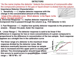
JFET Characteristic Curve • IV curve shows two areas of operation. • At low drain-source voltages it behaves like a variable resistance whose value is controlled by the applied gate-source voltage. • At higher drain-source voltages it passes a current whose value depends on the applied gate-source voltage. In most circuits it is used in this ‘high voltage’ region and acts as a voltage controlled current source.