Download

1 / 27
350 likes | 712 Views
FEM Modeling of Instrumented Indentation. MAE 5700: Finite Element Analysis for Mechanical and Aerospace Design. Joseph Carloni a , Julia Chen b , Jonathan Matheny c , Ashley Torres c a Materials Science PhD program, jdc357@cornell.edu

E N D
FEM Modeling of Instrumented Indentation MAE 5700: Finite Element Analysis for Mechanical and Aerospace Design Joseph Carlonia, Julia Chenb, Jonathan Mathenyc, Ashley Torresc aMaterials Science PhD program, jdc357@cornell.edu bMechanical Engineering PhD program, tc468@cornell.edu cBiomedicalEngineering PhD program, jbm299@cornell.edu, amt278@cornell.edu
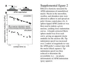
Introduction to instrumented indentation • A special form of indentation hardness testing where load vs. displacement data is collected continuously • The resulting load-displacement data can be used to determine the plastic and elastic properties of the material • Commonly used to test the elastic properties of a material, especially at a small scale “nanoindentation”
A Real NanoindentationExperiment 2. Indentation 1. Load Application 3. Load Removal
Nanoindentation Equations • The reduced modulus of contact between two materials is a function of the Young’s moduli: • Sneddon’s equation relates the reduced modulus of a contact to the contact stiffness and contact area: Sneddon, 1948 W.C. Oliver and G.M. Pharr (1992).
Motivation / Problem Statement • Sneddon’s equation was derived for contact between a rigid indenter and a “semi-infinite half space” • We want to model the elastic portion of an indentation in ANSYS so that we can vary dimensional parameters to see how they affect the accuracy of Sneddon’s equation P 2D Axisymmetric Ei, vi Es, vs h w
Solid Body Contact • Assume: strains are small, materials are elastic, surfaces are frictionless • Contact – is a changing-status nonlinearity. The stiffness, depends on whether the parts are touching or separated • We establish a relationship between the two surfaces to prevent them from passing through each other in the analysis termed, contact compatibility ANSYS® Academic Research, Release 14.5, Help System, Introduction to Contact Guide, ANSYS, Inc.
Normal Lagrange Formulation • Adds an extra degree of freedom (contact pressure) to satisfy contact compatibility • Contact force is solved for explicitly instead of using stiffness and penetration • Enforces zero/nearly-zero penetration with pressure DOF • Only applies to forces in directions Normal to contact surface • Direct solvers are used ANSYS® Academic Research, Release 14.5, Help System, Introduction to Contact Guide, ANSYS, Inc.
Penalty-Based Formulations Pros (+) and Cons (-) • Concept of contact stiffness knormalis used in both • The higher the contact stiffness, the lower the penetration • As long as xpenetration is small or negligible, the solution results will be accurate • The Augmented Lagrange method is less sensitive to the magnitude of the contact stiffness knormal because of λ (pressure) ANSYS® Academic Research, Release 14.5, Help System, Introduction to Contact Guide, ANSYS, Inc.
ANSYS Detection Method ANSYS® Academic Research, Release 14.5, Help System, Introduction to Contact Guide, ANSYS, Inc. • Allows you to choose the location of contact detection in order to obtain convergence • Normal Lagrange uses Nodal Detection, resulting in fewer points • Pure Penalty and Augmented Lagrange use Gauss point detection, resulting in more detection points
ANSYS Contact Stiffness • Normal stiffness can be automatically adjusted during the solution to enhance convergence at the end of each iteration • The Normal Contact Stiffness knormalis the most important parameter affecting accuracy and convergence behavior • Large value of stiffness gives more accuracy, but problem may be difficult to converge • If knormalis too large, the model may oscillate, contact surfaces would bounce off each other ANSYS® Academic Research, Release 14.5, Help System, Introduction to Contact Guide, ANSYS, Inc.
Nonlinear Finite Element Approach Loading Incrementation Procedure Newton-Raphson Iterative Method Becker, A.A. An Introductory Guide to Finite Element Analysis. p.109-125.
Initial problem set-up • Materials • Indenter- Diamond • Young’s Modulus=1.14E12 Pa • Poisson’s Ratio=0.07 • Tested Material- “Calcite” • Young’s Modulus=7E10 Pa • Poisson’s Ratio=0.3 • Both Materials Type • Isotropic Elasticity
Initial problem set-up • Axisymmetric Model • Boundary Conditions • Fixed displacement (in x) along axis of symmetry • Fixed support on bottom edge of material • Loading • Pressure (1E8 Pa) applied normal to top edge of indenter
ANSYS Default Mesh (10 divisions) Quadrilateral Elements
Refined Mesh (160 divisions) Quadrilateral Elements
Mesh Convergence The magnitude of the error converges Now we change other parameters
Final setup • Contact Type: Frictionless • Target Body: indenter • Contact Body: material • Behavior: Symmetric • Contact Formulation: Augmented Lagrange • Update Stiffness: Each Iteration • Stiffness factor: 1 • Auto time step: min 1, max 10 • Weak springs: off
Pressure Too high of a pressure increases the error
Dimension of material Too small of a sample increases the error
Different modulus Testing a high modulus material increases the error
Conclusion • Indentation can be accurately modeled using ANSYS and a well-refined mesh • The validity of Sneddon’s equation has been explored: • Lower pressure More accurate • Larger sample More accurate • More compliant sample More accurate