Instrumented Workboot for Measuring Impact Forces and Trajectories During Laborious Activities
This project focuses on developing an innovative instrumented work boot that accurately measures impact forces and trajectories when feet contact the ground during strenuous activities. Utilizing Tekscan force sensing resistors and 3-axis accelerometers, pressure and acceleration data are collected and converted into usable signals. The data is analyzed through a Graphical User Interface (GUI) for real-time feedback, and further evaluated using MATLAB for detailed insights. Direct applications include addressing back and knee injuries in the trucking industry, benefiting professionals in Podiatry and safety fields.

Instrumented Workboot for Measuring Impact Forces and Trajectories During Laborious Activities
E N D
Presentation Transcript
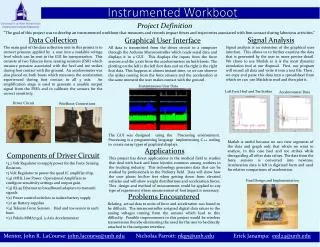
Project Definition “The goal of this project was to develop an instrumented workbootthat measures and records impact forces and trajectories associated with foot contact during laborious activities.” Data Collection The main goal of the data collection unit in this project is to convert pressure applied by a user into a readable voltage level which can be sent to the GUI for interpretation. This consists of two Tekscan force sensing resistors (FSR) which measure pressure associated with the heel and toe strikes during foot contact with the ground. An accelerometer was also placed on both boots which measures the acceleration experienced during foot contact in all 3 axis. An amplification stage is used to generate a useable output signal from the FSR’s and to calibrate the sensors for the correct sensitivity. Signal Analysis Graphical User Interface All data is transmitted from the driver circuit to a computer through the Arduino Microcontroller which reads serial data and displays it in a GUI. This displays the inputs from the force sensors and the 3 axis from the accelerometers on both boots. The plotting on the left is the left foot data and on the right is the right foot data. This happens at almost instant time, so we can observe the spikes coming from the force sensors and the acceleration at the same moment the user makes contact with the ground . Signal analysis is an extension of the graphical user interface. This allows us to further examine the data that is generated by the user in more precise detail. We chose to use Matlab as it is the most dynamic simulation tool at our disposal. First, our program will record all data and write it into a text file. Then , we copy and paste this data into a spreadsheet from which we can use Matlab to read and then plot it. Instrumented Workboot Instantaneous User Data Left Foot Heel and Toe Strikes Accelerometer Data Driver Circuit Workboot Connections The GUI was designed using the Processing environment. Processing is a programming language implementing C++ coding to create many types of graphical displays. Matlab is useful because we can view segments of the data and graph only that which we want to analyze, in this case heel and toe strikes while disregarding all other data values. The data from the force sensors is converted into newtons. Acceleration data is left in digitized form and used for relative comparisons of acceleration. Applications This project has direct applications in the medical field in studies that deal with back and knee injuries common among workers in the trucking industry. This technology generates data that can be studied by professionals in the Podiatry field. Data will show how the user plants his/her feet when getting down from elevated vehicles and will show weight distributions and acceleration forces. This design and method of measurement could be applied to any type of experiment where measurement of foot impact is necessary. • Components of Driver Circuit • 3.2 Volt Regulator to supply power for the Force Sensing Resistors. • 5 Volt Regulator to power the quad IC amplifier chip. • (4) 1MHz Low Power Operational Amplifiers to configure sensitivity settings and output gain. • (4) RJ-45 Ethernet to breadboard adapters to transmit signals • (2) Power control switches to isolate battery supply • (2) 9v Battery supplies • (4) Tekscan Force Sensors. Heel and toe sensor in each boot. • (2) Pololu MMA7341L 3-Axis Accelerometer Final Design and Implementation Problems Encountered Relating actual data to units of force and acceleration was found to be difficult. The microcontroller assigned digital data values to the analog voltages coming from the sensors which lead to this difficulty. Possible improvements to this project would be wireless transmission thereby eliminating the need for the user to be directly attached to the computer interface. Mentor, John R. LaCourse: john.lacourse@unh.edu Nicholas Parrott: nkg5@unh.edu Erick Janampa: eed24@unh.edu