Download
1 / 38
380 likes | 408 Views
This paper presents an overview of the design goals and key technologies for the High-Energy Large Hadron Collider (HE-LHC), including the use of FCC-hh magnet technology and high-luminosity collision experiments. Special attention is given to the tunnel integration and magnet technology, as well as the injector options and synchrotron radiation considerations.

E N D
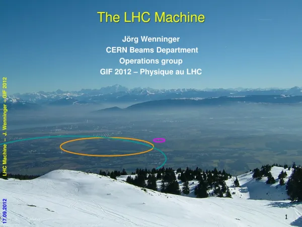
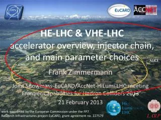
HE-LHC Machine Overview on behalf of the HE-LHC study group Frank Zimmermann, FCC Week 2018 Amsterdam, 9 April 2018 David Amorim, Sergey A. Antipov, Sergey Arsenyev, Michael Benedikt, Roderik Bruce, Matthew Crouch, StéphaneFartoukh, Massimo Giovannozzi, Brennan Goddard, Michael Hofer, Volker Mertens, Yvon Muttoni, John A. Osborne, Vittorio Parma, Vivien Raginel, Stefano Redaelli, Thys Risselada, Ingo Ruehl, Benoit Salvant, Daniel Schoerling, Elena Shaposhnikova, Laurent Tavian, Ezio Todesco, Rogelio Tomas, Davide Tommasini, Fani Valchkova-Georgieva, Valentina Venturi, Daniel Wollmann, Frank Zimmermann, CERN, Geneva, Switzerland; Gerardo Armen Apyan, ANSL, Yerevan, Armenia; Guillermo Canton, CINVESTAV Merida, Mexico; Florian Burkart, DESY, Hamburg, Germany; Javier Barranco, Lotta Mether, Tatiana Pieloni, Leonid Rivkin, Claudia Tambasco, EPFL, Lausanne, Switzerland; Jose L. Abelleira, Emilia Cruz-Alaniz, Pablo Martinez-Mirave, Andrei Seryi, Léon van Riesen-Haupt, JAI, Oxford, UK; Kazuhito Ohmi, Katsunobu Oide, Demin Zhou, KEK, Tsukuba, Japan; Yunhai Cai, Yuri Nosochkov, SLAC, Menlo Park, U.S.A. thanks to Oliver Brüning (CERN), Daniel Schulte (CERN), Vladimir Shiltsev (FNAL), Jörg Wenninger (CERN)
HE-LHC design goals and basic choices HE-LHC design goals & basic choices physics goals: • 2x LHC collision energy with FCC-hh magnet technology • c.m. energy = 27 TeV 14 TeVx 16 T/8.33T • target luminosity ≥ 10 ab-1 over 20 years key technologies: • FCC-hh magnets & FCC-hhvacuum system • HL-LHC crab cavities & long-range wire compensation beam: • HL-LHC/LIU parameters (25 ns baseline)
HE-LHC layout like LHC LHC 8 interaction regions (IRs) 2 high-luminosity experiments in IR1 & 5 2 secondary experiments (perhaps including one e-p collision point) in IRs 2 & 8, shared with injection IR3: momentum collimation IR4: radiofrequency (RF) and diagnostics IR6: beam extraction IR7: betatron collimation
HE-LHC: topics requiring special attention many aspects extrapolated/copied from HL-LHC or FCC-hh. most important exceptions: tunnelintegration and magnet technology • push for compact 16 T magnets (magnetic cryostat, shielding) (LHC tunnel 3.8 m vs. FCC-hh 5.5 m) • HE-LHC Nb3Sn magnets must be bent - 9 mm horizontal orbit shift over 14 m (vs. 2 mm for FCC-hh) arcoptics • high dipole filling factor to reach energy target, or strong focusing for lower energy injection • acceptable strength of quadrupoles and sextupoles • dynamic aperture, beam size, apertures at injection straights • low-beta insertions, longer triplet than HL-LHC, b* reach • collimation insertions, LHC or FCC-hh optics scaling not applicable, warm dipole length increase • extraction straights – length of kicker & septum sections injector and injection energy • physical & dynamic aperture, impedance and beam stability, swing of 16 T magnets… M. Benedikt
arc half cells: LHC vs HE-LHC J. Keintzel
arc optics: two strategies lowest injection energy (more shorter cells, “LHC-like”) highest energy reach = lowest dipole field (fewer longer cells) M. Hofer, J. Keintzel, R. Tomas, Y. Nosochkov, T. Risselada, D. Zhou * 18 cells per arc, with 90 deg phase advance / cell ** 23 cells per arc, with 90 deg phase advance / cell
transition arc to straight 1st arc cell dispersion suppressor J. Keintzel
HE-LHC injector options North Area • inject from present SPS at 450 GeV concerns: • physical aperture (1/2-2/3 of LHC), machine protection,… - energy swing (field quality at low energy) - instabilities alternatives: 2. new fast ramping SC SPS with single-layer SC dipole (scSPS), max. field 4 T → extract at 900 GeV 3. scSPS with double-layer SC dipole, max. field 6 T → extract at 1.3 TeV downsides: large energy swing in scSPS, also new transfer-line magnets from scSPS to HE-LHC LSS3 RF LSS4 Fast extraction LSS2 Slow extraction LSS5 Collimation LSS1 Injection LSS6 Fast extraction & Beam dump F. Burkart, B. Goddard
HE-LHC arc synchrotron radiation R. Kersevan HE-LHC photon flux per meter = 5.4x LHC (7 TeV) and 1.8x FCC-hh (50 TeV) → beam-screen to intercept synchrotron radiation at higher T and cryo-pumping R. Kersevan
arc beam-screen cooling channel HE-LHC beam-screenpressure drop HE-LHC electrical power to refrigerator vs pressure drop use the FCC-hh design which is compatible with a 20 bar operating pressure 2 circular cooling channels per BS (LHC like) mass flow per cooling channel: ~ 5 g/s for exergetic efficiency: DP < ~5 % of operating pressure equivalent FCC BS design LHC size L. Tavian
arc aperture & beam size at injection FCC-hh type beam screen: important for vacuum, cryogenics, and impedance HE-LHC vs LHC beam screen R. Kersevan S. Arsenyev, D. Schulte L. Tavian G. Guillermo horizontalbeam size (6s) in arcs (QF) at injection HL-LHC FCC-hh 3.3 TeV HE-LHC 450 GeV HE-LHC 1.3 TeV
normalized arc aperture at 450 GeV J. Keintzel eN=2.5 mm w/o dipole b2 errors hierarchy: secondary collimators, dump protection M. Hofer R. Bruce, S. Redaelli
field quality 1.3 TeV 450 GeV sextupolarand decapolar multipole errors b3 and b5 for the 16 T dipole magnets as function of field strength for an effective Nb3Sn filament size of 50 µm (blue) or 20 µm (red). sextupolecomponent b3 in the main arc dipoles, in units of 10−4 at a radius of 16.7 mm S. Izquierdo B., D. Schoerling
dynamic aperture M. Hofer, Y. Nosochkov 105 turns, 60 seeds, Dp/p=7.5x10-4 solution(s) found for 1.3 TeV injection D. Schoerling, R. Tomas, S. Fartoukh potential solutions: active pinning centres, iron shims, HTS shims, sorting, larger number of corrector families • requirement/goals for 450 GeV injection: • reduce systematic b2 by factor 3 • reduce random b3 to <10 units at all energies • reduce random b5
HE-LHC final-focus layout (IR 1 & 5) LHC HL-LHC HE-LHC 7 T 11T space for crab cavities (6 MV) L. van RiesenHaupt
squeezed IR optics & aperture beta function and apertures for the squeezed optics at collision energy in the experimental IRs 1 and 5, for a half crossing angle of 131 µrad, including a 2 mm closed-orbit uncertainty. L. van RiesenHaupt
triplet radiation, shielding & lifetime • triplet quadrupoles with 2 cm inside tungsten shielding • for 10 ab-1 total luminosity: 30-40 MGy peak radiation (peak at interconnect can be reduced with shielding) FLUKA model of the final triplet quadrupoles peak dose along the final quadrupole triplet for 10 ab−1 and a half crossing angle of 140 µrad, as simulated by FLUKA J. Abelleira
betatron collimation IR7 • recipe: • replace outer • dogleg dipoles • by SC ones • push strength of • and lengthen other • dipoles and quads • remove weak magnets • use empty space preliminary HE-LHC IR7 optics LHC HE-LHC longer MBWs SC longer, stronger MQWs & weak ones removed ? next steps: iteration with magnet designers, shielding model, and FLUKA simulations M. Crouch
collimation cleaning efficiency zoomed view of IR7 entire ring need for collimators in the dispersion suppressor as for HL-LHC, to avoid losses in cold magnets LHC target simulated particle losses around HE-LHC for a scaled “LHC” betatron cleaning insertion (scaled aperture and energy) M. Crouch
optics for other IRs IR2 – injection & secondary exp. IR4 – instrumentation & RF IR6 – beam extraction J. Keintzel, W. Bartmann, P. Mirave, B. Goddard, L. van RiesenHaupt,….
extraction and injection kickers key parameters of LHC and HE-LHC extraction kickers in IR6 extraction kicker system easier for higher injection energy injection kicker system longer for higher injection energy → less space for secondary experiments? key parameters of LHC and HE-LHC injection kickers in IR2 and IR8 W. Bartmann, B. Goddard, E. Renner, M. Barnes
longitudinal parameters RF voltage (solid line) and emittance with controlled blow up (dashed line) during the 20-minute ramp from 450 GeV to 13.5 TeV. A transition energy gtof 53.8 is assumed. RF power requirements do not exceed those of HL-LHC E. Shaposhnikova
transverse impedance at 450 GeV HE-LHC impedance = 2-3× LHC impedance due to changes in the beam screen (size & temperature) D. Amorim, S. Antipov, S. Arsenyev Real (solid) and imaginary part (dashed curves) of HE-LHC transverse impedance at two different injection energies compared with the HL-LHC transverse impedance, as a function of frequency.
conventional instabilities Stability limits explored with Vlasov solvers (NHT and DELPHI): At 450 GeV: feedback damping time < 50 turns needed TMCI threshold 7 × 10¹¹ppb for single bunch, 4 × 10ppb for multi bunch, still 2× design Growth rate of the most unstable mode ImΔω/ωs for Nb = 2.2 × 10¹¹ protons per bunch and 2748 bunches as a function of chromaticity Q′ and damper gain g (left) and as a function Q′ and Nbwith a 50-turn damper (right) at 450 GeV. S. Antipov, D. Amorim, S. Arsenyev, B. Salvant, et al.
electron cloud central electron density heat load 13.5TeV 13.5TeV single-bunch instability threshold maximum secondary emission yield L. Mether
long-range & head-on beam-beam long-range wire compensation may allow for smaller crossing angle (qc/2130 mrad) Separation at long-range encounters for the HE-LHC with 180 µrad half crossing angle, compared with the HL-LHC and the LHC configuration of 2012. Beam-beam tune footprint up to 6σ in transverse amplitude for HE-LHC with 180 µrad half crossing angle, compared with HL-LHC and 2012 LHC configuration. T. Pieloni, C. Tambasco
24 hours at the HE-LHC optimum fill length 3 h 6 fb-1 on a good day
luminosity / year vs turnaround time • HE-LHC assumptions: • 160 days scheduled • for physics / year • 70% availability • → 30% of time in physics • for comparison • LHC 2017: • 82.9% availability • 49% of time in physics nominal turnaround
HE-LHeC: e- configuration like LHeC O. Brüning, J. Jowett, M. Klein, D. Pellegrini, D. Schulte, F.Z.
HE-LHeC parameters parameters and estimated peak luminosities of future electron-proton collider configurations based on an electron ERL, esp. HE-LHeC, when used in concurrent ep and pp operation mode O. Brüning, J. Jowett, M. Klein, D. Pellegrini, D. Schulte, F.Z.
HE-LHC conclusions • optics solution with injection at 1.3 TeV & top energy 13.5 TeV (nearly) at hand; would require sc SPS as injector • investigating alternative with injection at 450 GeV, maximum energy 13 TeV • related magnet design improvements under study (APC’s, shims,…) • dynamic aperture, machine protection and collimation system challenging • HE-LHC magnets, integration, and cryogenics not trivial • collective effects mostly under control a great team and getting stronger
thank you ! hartelijk dank !
HE-LHC integration aspects working hypothesis for HE LHC design: no major CE modifications on tunnel and caverns • similargeometry and layout as LHC machine and experiments • maximum magnet cryostat external diameter compatible with LHC tunnel 1200 mm • lassical cryostat design gives 1500 mm diameter! LHC tunnel diameter 3.8 m strategy: develop optimized 16 T magnet, compatible with both HE LHC and FCC-hh requirements: • allow stray-field and/or cryostat as return-yoke • optimizationof inter-beam distance (compact) smaller diameter also relevant for FCC-hh cost V. Mertens
16 T cryo-dipole integration approach design evolution • coil optimization and margin 18 14% • inter-beam distance 250 204 mm stray-field < 0.1 T at cryostat fringe field – x axis [T] cold mass 40t total mass 62t 800 mm 600 mm cosine-theta (baseline) 0 700 Field [T] HE-LHC “stray field task force” found no showstopper block-type coils 0.06 T at cryostat edge 600 mm radius common-coils D. Tommasini, D. Schoerling distance from yoke [mm] 2015 2017
HE-LHC cryogenic layout half-sector cooling instead of full sector (as for LHC) to limit cross section of cryogenic distribution line higher heat load and integration limitations (Cryo-line diameter) requires installation of 8 additional 1.8 K refrigeration units wrt. LHC • 2.3 kW @ 1.8 K (~ LHC size) • P elect: ~500 kW per unit 8 new higher-power 4.5 K cryoplants • 28 kW @ 4.5 K (including 2.3 kW @ 1.8 K) • P elect: ~6500 kW per cryoplant(cf. 4200 kW for LHC cryoplant) L. Tavian