Download

1 / 53
540 likes | 912 Views
Full custom design of aN fpga. Jongsok Choi M.A.Sc Candidate, University of Toronto. Overview. TSMC 0.35 um technology Cadence tools Less than 2mm X 2mm die area Design time = 1 month Tile based approach Each tile contains a Logic Block,

E N D
Full custom design of aNfpga Jongsok Choi M.A.Sc Candidate, University of Toronto
Overview • TSMC 0.35 um technology • Cadence tools • Less than 2mm X 2mm die area • Design time = 1 month • Tile based approach • Each tile contains a Logic Block, 2 Connections Blocks and a Switch Box • Pass transistor approach 2
References • Architecture and CAD for Deep-Submicron FPGAs 3
Presentation Outline • Schematics • Base Cells – Pass transistor, SRAM, Multiplexer • Logic Block – LUT, Set/Reset Logic, D-flipflop • Connection Box – Right, Bottom • Switch Box • Tile 2X2 • Programming Circuitry – Row, Column • FPGA 4X4 – Programming a multiplier • FPGA 32X16 – full schematic • Layouts • Base Cells – SRAM, Multiplexer, Pull-up Buffer • Logic Block – LUT, Set/Reset Logic, D-flipflop • Connection Box – Right, Bottom • Programming Circuitry – Row, Column • Tile – Single tile, Tile 2X2 • FPGA 4X4 – Post-layout simulation of programmed multiplier • FPGA 32X16 – floor plan, full layout • Clock tree – H-tree implemented • Complete layout with Padframe • DRC, LVS Results • Employed layout techniques and Conclusions
Base Cells Highlighted red boxes in the top right hand corner indicate where this cell is used (e.g. Pass transistor is used in the logic element, connection boxes 1 and 2, and the switch block) • Pass transistor • Schematic • Simulation 6
Base Cells • SRAM cell : to program the FPGA with the required functionality • Schematic • Simulation 7
Base Cells • 2-to-1 Multiplexer • Schematic: • Simulation 8
Base Cells • 4-to-1 Multiplexer: to choose between the four SRAM bits in the LUT • Schematic • Simulation 9
Logic Block • Top-level Schematic 10
Logic Block - LUT • Schematic • Simulation 11
Logic Block – Set/Reset Logic • Schematic: • Simulation • When Sram 1, 2 set to ‘1’ => Set= 1 • When Sram 1, 2 set to ‘0’ => Reset= 1 12
Logic Block – D-Flip Flop • Schematic • Simulation 13
Connection Box -Right • Functionality: Connect vertical tracks to logic element • Schematic • Simulation • Track2 selected when SRAM set to ‘0’ • Track1 selected when SRAM set to ‘1’ 14
Connection Box -Bottom • Top Level Schematic • Output from CB to Tracks • Input to CB from Tracks 15
Switch Box • Schematic 16
TILE 2x2 • Schematic: • Each tile has different connections at the switch box • Segmented and staggered routing structure for FPGA • Segment Length of 2 V1 V2 V3 V4 H1 H2 H3 H4 17
Programming Circuitry – Programming Column • Schematic • Simulation 18
Programming Circuitry – Programming Row • Schematic • Simulation 19
FPGA 4x4 • Schematic 20
FPGA 4x4 • FPGA Mapping and Programming bits for a 2 by 2 Multiplier • Table shows manually created bitstream to program the multiplier using 4X4 tiles with programming circuits 21
0 0 0 0 1 1 1 1 2 2 2 2 3 3 3 3 FPGA 4x4 • Simulation • 2 by 2 Multiplier correctly implemented • Shows correct output for all possible inputs Bit[3] Bit[2] Bit[1] Numbers shows total output Bit[0] 0 1 2 3 0 2 4 6 0 3 6 9 Input 1 0 1 2 3 Input 2 22
Layouts 24
Base Cells • SRAM cell : to program the FPGA with the required functionality • Schematic • Layout 25
Base Cells • 4-to-1 Multiplexer: to choose between the four SRAM bits in the LUT • Schematic • Layout 26
Base Cells • Pull-up buffer: used to pull the degraded signal back up to VDD • Layout 27
Logic Block • Top-level Schematic 28
Logic Block - LUT • Layout • Schematic • Layout 29
Logic Block – Set/Reset Logic • Schematic • Layout 30
Logic Block – D-flipflop • Schematic • Layout 31
Logic Block • Layout Buffer_inverter for clock LUT Set/Reset D-flipflop Pullup Buffer 32
Connection Box -Right • Schematic • Layout 33
Connection Box - Bottom • Top-level Schematic • Output from Connection box to Tracks 34
Programming Circuitry – Programming Column • Schematic • Layout 35
Programming Circuitry – Programming Row • Schematic • Layout 37
Tile • Schematic 39
Tile -Layout Logic Element Right Connection Box Bottom Connection Box Switch Box 40
FPGA 4x4 - Post Layout Simulation • FPGA Mapping and Programming bits for a 2 by 2 Multiplier • Table shows manually created bitstream to program the multiplier using 4X4 tiles with programming circuits 43
0 0 0 0 1 1 1 1 2 2 2 2 3 3 3 3 FPGA 4x4 – Post-Layout Simulation • Post-Layout Simulation • 2 by 2 Multiplier correctly implemented • Shows correct output for all possible inputs • Matches schematic simulations Input 1 0 1 2 3 Input 2 Numbers shows total output 0 1 2 3 0 2 4 6 0 3 6 9 Bit[0] Bit[1] Bit[2] Bit[3] 44
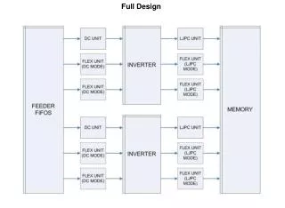
Programming Column Programming Row 4x4 Tile 4x4 Tile 4x4 Tile 4x4 Tile 4x4 Tile 4x4 Tile 4x4 Tile 4x4 Tile 1.525 mm 4x4 Tile 4x4 Tile 4x4 Tile 4x4 Tile 4x4 Tile 4x4 Tile 4x4 Tile 4x4 Tile 1.525 mm 4x4 Tile 4x4 Tile 4x4 Tile 4x4 Tile 4x4 Tile 4x4 Tile 4x4 Tile 4x4 Tile 1.525 mm 4x4 Tile 4x4 Tile 4x4 Tile 4x4 Tile 4x4 Tile 4x4 Tile 4x4 Tile 4x4 Tile 1.25 mm 32x16 Tiles FPGA Floorplan 45
Clock Tree • H-tree structure • Perfectly symmetrical in every direction to reduce clock skew 47
DRC - Passed 49
LVS - Passed 50