Connecting a Sensor to a Computer using a microcontroller
Connecting a Sensor to a Computer using a microcontroller. By: James Kloss Erik Amaral Zach Baron. Objective. Design a sensor Connect the sensor to a computer. Microcontroller. A microcontroller will: Convert analog signal to digital Report the digital data to the computer

Connecting a Sensor to a Computer using a microcontroller
E N D
Presentation Transcript
Connecting a Sensor to a Computer using a microcontroller By: James Kloss Erik Amaral Zach Baron
Objective • Design a sensor • Connect the sensor to a computer
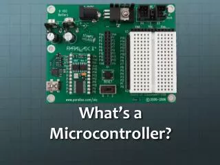
Microcontroller • A microcontroller will: • Convert analog signal to digital • Report the digital data to the computer • Provide a platform to build the sensor circuit on • Hold program information
Common Microcontrollers • MSP430 • Arduino • BasicX • Stellaris • AVR BasicX Stellaris AVR
Which one is best? • There are hundreds of different microcontrollers • We used an arduino and the MSP430
Look Online! • You can find microprocessors and sensors online very cheap. • We purchased our Arduino online for $25 from a www.sparkfun.com • They also have a wide variety of sensors that may be useful for further projects.
Wiring the Sensor to the Microcontroller Make a Voltage divider
Original Circuit Using MSP430 Vcc=Vin Vss=Pin 5=Ground Pin4=Vnode
Basic Single Sensor Configuration • Arduino:
Programming the Microcontroller • All microcontrollers have an IDE for uploading program information • Integrated Development Environment (IDE) • IAR Embedded workbench • Arduino Alpha
Download The IDE Arduino MSP430 IAR: Insert CD. Be sure to have an internet connection Select IDE software tab Select IAR Embedded workbench • Arduino: http://arduino.cc/en/Main/Software • Select the appropriate version of Arduino Alpha according to your computer specifications
It should look like this Arduino MSP430 This is what will appear once the cd is inserted • If you are using your WIT laptop select “Windows”
Completing the Download Arduino MSP-430 Click the start menu and type UAC in the search bar Box appears, scroll cursor to “Never Notify” and click ok • Open the downloaded file and select “Extract Files” • The Arduino software is now installed.
Installing the Drivers • Plug the MSP430 or the Arduino into any USB drive • Click on the “Found new Hardware” bubble • Select “Install from a list or specific location” • Check the box labeled “include this location in the search”
Port Identification • In the start menu select “control panel” then “Device Manager” • Click on “Ports” (the MSP will display as MSP430FETUIF
Identifying the Port on the IDE Arduino MSP430 Download Sample Programs for the MSP430 at www.designsmsp430.com Register with the website In the lower right hand corner under MCU Resources select code examples/ libraries Download MSP430Fxxxx • After identifying the Port the Arduino is connected select the port in the Arduino IDE under the “Tool” bar
Writing the Program Arduino MSP430 Beginyour sketch in the MSP430 IDE by selecting create new project in C main The command statements are as follows: -Serial -Void -int -val -analogRead -Println() -Delay
Arduino is Finished • Here is the compiled code for the Arduino. To view the sensor output click “serial monitor” below and to the right of the “Help” tool bar. Be sure to set “baud” to 9600 after clicking serial monitor • intval = 0; • void setup () { • Serial.begin(9600); • } • void loop() { • val = analogRead(0); • Serial.println(val); • delay (100); • }
Final Steps for the MSP430 • After opening new project in “C” “Main” save the project as ADC_setLED • Press Ctrl+O • Search for the file named “msp430x20x3_sd16A_01.c”in the folder msp430F20xx code examples and open it
Save the Copied program • Copy all of the code and paste it into the “main.c” and close the other workspace • Save “main.c” as the name of the (ADC_setLED) • Right click on the project and and click add. Select ADC_setLED and remove “main.c”
Compile, Debug and Run • Click compile to make sure there are no errors in the program • Click Debug and the program will begin running. • To view the SD16MEM0 click the “view” tab and select “Register” • In the Register select sd16_A1
The MSP430 is Finished • Here is what It should look like
Multiple Sensor Configuration Arduino
The Software • void setup(){ • Serial.begin(9600); } • void loop(){ • Serial.print("a"); Serial.print(analogRead(0)); Serial.print(" "); Serial.print("b"); Serial.print(analogRead(1)); Serial.print(" "); Serial.print("c"); Serial.print(analogRead(2)); Serial.print(" "); Serial.print("d"); Serial.print(analogRead(3)); Serial.print(" "); Serial.print("e"); Serial.print(analogRead(4)); Serial.print(" "); Serial.print("f"); Serial.print(analogRead(5)); Serial.print(" "); //print carriage return and newline Serial.println(); delay(20); }