Download
1 / 72
990 likes | 1.71k Views
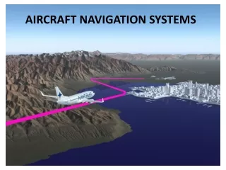
AIRCRAFT NAVIGATION SYSTEMS. Navigation Systems. Navigation by Pilotage – Visual Navigation. Celestial Navigation – Based on the position (azimuth and elevation) of celestial bodies in space.

E N D
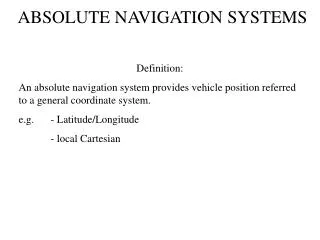
Navigation Systems Navigation by Pilotage – Visual Navigation. Celestial Navigation – Based on the position (azimuth and elevation) of celestial bodies in space. Radio Navigation – Very High Frequency OmniRange (VOR), Distance Measuring Equipment (DME), Automatic Direction Finding (ADF), Tactical Air Navigation (TACAN), Long Range Navigation (LORAN), VORTAC (Combined VOR and TACAN). Dead reckoning navigation – Inertial Navigation System (INS) and Doppler Navigation. Global Navigation Satellite Systems (GNSS) – NAVSTAR GPS, Russian GLONASS, European Union’s Galileo. Approach and Landing Aids – Instrument Landing System and Microwave Landing System.
Automatic Direction Finder It operates in Low Frequency and Medium Frequency band (190-1799 KHz), thus it is based on ground wave propagation. Its range is not limited to line-of sight distance. It can receive on both Amplitude Modulation radio stations and NDB (non directional beacons). Its operation is similar to listening to a transistor radio. ADF Ground station – transmit omnidirectional signals. They are called nondirectional beacons (NDB). Stations have a vertical antenna which emits vertically polarized signal. ADF Aircraft components – Antennas, Receiver, Control head, Indicator. ADF antennas – Loop antenna (directional antenna), Sense antenna (omnidirectional antenna).
Automatic Direction Finder Radio wave transmission from NDB
Automatic Direction Finder Rectangular loop antenna Circular loop antenna
Automatic Direction Finder Typical Radio Magnetic Indicator (RMI)
Automatic Direction Finder Typical Radio Magnetic Indicator (RMI)
VHF Omni Range (VOR) VOR enables a pilot to determine the direction of his aircraft from any position to or from a VOR beacon – actually giving bearing information – after that a ‘position fix’. VOR is a VHF navigation aid which operates in the 108 to 117.95 MHz frequency band. Because it is a VHF aid, its ground to air range is limited to line of sight reception which is typical of VHF transmission. An infinite number of bearings can be obtained and they may be visualized as radiating from the beacon like spokes from the hub of a wheel. The number of bearings can be considered to be limited to 360 degrees, one degree apart (like spokes in a wheel), and these 360 bearings are known as radials.
VHF Omni Range (VOR) VOR – 360 radials
VHF Omni Range (VOR) The VOR beacon transmits two different radio signals in VHF carrier (108–118 MHz) from the same facility. One of these signals, called the reference signal, is omni-directional and radiates from the station in a circular pattern.The phase of this signal is constant through 360° of azimuth. The other signal is transmitted as a rotating field. This signal pattern rotates uniformly at 1800 rpm (30 rps) through 360 degrees (like the beam from the lighthouse), varies in phase with azimuth, and is called the variable signal. The variable signal is 30 Hz amplitude modulated directly in VHF carrier whereas the reference signal is 9960 Hz subcarrier which is frequency modulated at 30 Hz which in turn amplitude modulated in VHF carrier. Therefore, there is a different phase of the variable signal at each separate point around the station.
VHF Omni Range (VOR) VOR phase angle relationships
VHF Omni Range (VOR) Components of VOR signals
VHF Omni Range (VOR) VOR Indicator
Distance Measuring Equipment (DME) DME is a secondary Radar and provides distance (slant range) information. VOR/DME System – Frequency Pairing. Interrogator (aircraft) – frequency f1 and Transponder (ground beacon) – frequency f2. Pulse repetition frequency (PRF) – here pulse pair, unique for an aircraft. Range (nautical mile) = (t–d)/12.36 μs, d = 50 μs.
Distance Measuring Equipment (DME) DME – Principle of operation
Distance Measuring Equipment (DME) Automatic gain control and constant duty cycle operation – Squitters (noise pulses or ‘filler’ pulses). The DME interrogator operates in the band 1025–1150 MHz with 126 channels with 1 MHz spacing. The transponder operates in the band 962–1213 MHz. For each channel, pair of frequencies (f1 and f2) which differ by 63 MHz are allotted. The frequency of 63 MHz is used as the intermediate frequency in the receivers. X and Y modes (channel) of transmissions. Both the interrogator and transponder operate with pulse pairs consisting of two pulses 12 μs apart.
Distance Measuring Equipment (DME) DME – X mode (channel) DME – X mode (channel) reply interrogation
Distance Measuring Equipment (DME) DME – Y mode (channel) DME – Y mode (channel) reply interrogation
Long Range Navigation (LORAN) It is an electronic system of land-based transmitters broadcasting low frequency pulsed signals that enable ships and aircraft to determine their position. Standard loran or Loran-A system operated in the frequency range 1850–1950 kHz with master and slave stations separated by up to 600 nmiles. Coverage of the system used ground waves at ranges from 600 to 900 nmiles over seawater by day, and between 1250 and 1500 nmiles via sky wave reception at night. Loran-A chains operate by measuring the difference in time arrival of the pulses from the master and the slave stations. Every time difference produces a line of position (LOP) for a master-slave pair and a positional fix is obtained by the intersection of two such LOPs using two suitable master-slave pairs.
Long Range Navigation (LORAN) Loran-A chains are identified by an alphanumeric which specifies the transmission frequency and the pulse repetition rate (determined by the number of pulses transmitted per second). The pulse repetition rate differs between station pairs in the same chain. Loran-A was finally phased out in 1980 and replaced by Loran-C. Loran-C operates in LF band of 90–110 kHz. Loran-A pulse width 40 ms, Loran-C pulse width 250 ms.
Long Range Navigation (LORAN) LOPs produced from two transmitter stations (separated by 1800 km) emitting pulses simultaneously
Long Range Navigation (LORAN) Modification of the LOPs – Station B is not allowed to transmit until triggered by a pulse from Station A
Long Range Navigation (LORAN) Coding delay and Emission delay (or Absolute delay). Further Modification to the LOPs – Station B with Coding delay (1000 ms in this example)
Long Range Navigation (LORAN) Position fixing using LOPs from two pairs of master/secondary stations
Long Range Navigation (LORAN) LORAN-C pulses
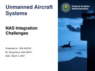
Global Positioning System The Global Positioning System (GPS) is a satellite-based navigation system that was developed by the U.S. Department of Defense (DoD) in the early 1970s. Initially, GPS was developed as a military system to fulfil U.S. military needs. However, it was later made available to civilians, and is now a dual-use system that can be accessed by both military and civilian users. GPS provides continuous positioning and timing information, anywhere in the world under any weather conditions. GPS is a one-way-ranging. That is, users can only receive the satellite signals.
GPS Orbits GPS consists, nominally, of a constellation of 24 operational satellites around six orbits with four or more satellites each. The satellite altitude is about 20,200 km above the Earth's surface. GPS satellite orbits are nearly circular (an elliptical shape with a maximum eccentricity is about 0.01), with an inclination of about 55° to the equator. The corresponding GPS satellite orbital period is about 12 sidereal hours.
GPS Space Segment The space segment consists of the 24-satellite constellation. Each GPS satellite transmits a signal, which has a number of components: two sine waves (also known as carrier frequencies), two digital codes, and a navigation message. The codes and the navigation message are added to the carriers as binary biphase modulations. The carriers and the codes are used mainly to determine the distance from the user's receiver to the GPS satellites. The navigation message contains, along with other information, the coordinates (the location) of the satellites as a function of time. The transmitted signals are controlled by highly accurate atomic (cesium and/or rubidium) clocks onboard the satellites to provide timing information for the satellite signals.
GPS Space Segment GPS signals – L1 signal with carrier frequency of 1575.42 MHz and L2 signal with carrier frequency of 1227.6 MHz. C/A (Coarse Acquisition) – PRN 1.023 MHz (SPS) and P (Precision) – 10.23 MHz (PPS) digital codes.
GPS Control Segment The control segment of the GPS system consists of a worldwide network of tracking stations, with a master control station (MCS) located in the United States at Colorado Springs, Colorado. The monitor stations measure signals from the satellites which are incorporated into orbital models for each satellite. The models compute precise orbital data (ephemeris) and clock corrections for each satellite. The Master Control station uploads ephemeris and clock data to the satellites through the S-band link. The satellites then send subsets of the orbital ephemeris data to GPS receivers over radio signals.
GPS Control Segment GPS control sites
GPS Position Determination 3D-Trilateration Pseudorange
Software based GPS Receiver Architecture of Software-based GPS Receiver
GPS Error Sources Satellite clock errors. Satellite ephemeris errors. Atmospheric errors – Ionosphere and Troposphere. Multipath errors. Receiver clock errors.
Inertial Navigation A form of Dead Reckoning navigation. Most commonly used in all aerospace, land, sea and underwater vehicles. Rely on Inertial reference frame, Inertial sensors and Coordinate systems (or reference frames). Inertial navigation principle – Inertial properties – Acceleration – Mathematical integrations (provided the initial conditions) The inertial sensor which measures the acceleration (linear) is known as an accelerometer (primary sensor in inertial navigation). Is accelerometer alone be used in inertial navigation???
Inertial Navigation – Reference Frames Inertial frame ECEF (XYZ) and NEU/NED frame Body frame
Inertial Navigation In order to navigate with respect to inertial reference frame, it is necessary to keep track of the direction in which the accelerometers are pointing. Rotational motion of the body with respect to the inertial reference frame can be sensed by using an inertial sensor called gyroscope (or gyro) and it is used to determine the orientation of the accelerometers at all times. Given this information, it is possible to resolve the accelerations into the reference frame before the integration process takes place.
Inertial Navigation – Mechanization The main problem in INS is that the accelerometer cannot tell the difference between vehicle acceleration and gravity. We therefore have to find a way of separating the effect of gravity and the effect of acceleration. This problem is solved in one of the two ways: Keep the accelerometers horizontal so that they do not sense the gravity vector. This is the stable platform (Gimbal) mechanization. Somehow keep track of the angle between the accelerometer axis and the gravity vector and subtract out the gravity component. This is the strapdown mechanization.
Inertial Navigation – Mechanization Stable platform (or gimbal) mechanization
Inertial Navigation – Gimbal Mechanization Gimbal Lock and Gimbal error.