System Integration in Mechatronics Engineering: Designing Integrated Systems
2.85k likes | 2.98k Views
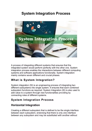
Dr. Osama Al-Habahbeh discusses system engineering and integration in mechatronics. Learn about system architecture, integration processes, lifecycle management, and design steps. Explore commonality and design specifications for quality and efficiency.

System Integration in Mechatronics Engineering: Designing Integrated Systems
E N D
Presentation Transcript
University of JordanSchool of EngineeringMechatronics Engineering DepartmentDesign of Integrated SystemsDr. Osama M. Al-HabahbehSpring Semester 2016/2017 Dr. Osama Habahbeh
System Integration • Introduction : System Engineering : Examples of complex engineering systems: include jet airplanes, aircraft carriers, submarines, space shuttles, information systems, cars, mobile phones, etc.… Dr. Osama Habahbeh
System Integration • A system is defined as a set of elements that work together to produce results not obtainable by individual elements. • The elements could include people, hardware, software, facilities, policies and documents. • The results include system level characteristics and performance and they depend on how the elements are interconnected. • A system can be devided into subsystems, and a subsystem can be devided into components or parts. Dr. Osama Habahbeh
System Integration • System engineering is an interdisciplinary field that integrates all the efforts to develop and verify a set of system, people, product, and process solutions that satisfy customer needs. • The system engineering process starts with the user requirement analysis, then system requirement analysis, then system design. Dr. Osama Habahbeh
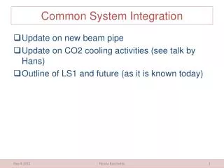
System Integration • The components development, then system integration validation, and verification. • The system engineering process has dynamic nature, that is : iterative and incremental not sequential. • A requirement can be mentioned in a contracted, a standard. A specification, or a regulation. • A requirement should be necessary, verification and attainable. • System architecture identify performance requirements, while physical architecture depicts the products subsystems and components. • System integration means bringing the subsystems and components together so that they work as a whole. Dr. Osama Habahbeh
System Integration • System Engineering (SE) is a moving from documents based to model based. • The system life cycle starts with the concept, then development, then production, then operation and support. Dr. Osama Habahbeh
System Integration • Each of these stages can be modeled, and the resulting models can be integrated. • Part 2: • Product Lifecycle : • Product lifecycle is triggered by a market need or a main idea. • It starts with product planning, and ends with disposal. Dr. Osama Habahbeh
Market need Goals of company Product Planning Design/development Production/Assembly/Test Requirements Product Lifecycle management Marketing/Sales Use/Consumption/Maintenance Recycling Disposal/Environment Dr. Osama Habahbeh
Structure of system: S:SystemBoundary I/P 1 O/P 1 I/P 2 O/P 2 I/P 3 Dr. Osama Habahbeh
Structure of system • ,, and are subsystems of S. • ,, and are subsystems of . • I/P 1, I/P 2, and I/P 3 are inputs. • O/P 1 and O/P 2 are outputs. • Transfer function can be used to express the static and dynamic behavior of the elements (Subsystems) of the system model. Dr. Osama Habahbeh
System Life Phases System Replacement Preliminary Study System Development System Production System Installation System Operation Planning Problem Analysis Problem formulation System Synthesis System Analysis Evaluation Decision The System approach is iterative goes in cycles Dr. Osama Habahbeh
System Design Steps • Product Design Specification (PDS) is based on market need. Abstract Costing Requirements Planning Synthesis Concept Design DetailedDesign Market Need Specifications (PDS) -Optimization -Simulation Embodiment Design Iterations Competition Analysis Prototyping Testing Dr. Osama Habahbeh
Top-Down System Design: Sub-functions A set of parts or subsystems Decomposing Function Structures Requirements/Objectives Integrated System Integrating The Subsystems Building the subsystems Dr. Osama Habahbeh
Interface Identification • Good interface design between subsystems is essential for correct functionality of the whole systems , Compatibility of subsystems and components. • Example of interface include electrical signals damage and dust protection (case), air cooling, user display, user control, mounting supports, power input, etc.… • Some interface are external and others are internal (with the system), such as joining subsystems. Dr. Osama Habahbeh
System Integrity • Means the system is organized to meet quality and consistency standards, with an acceptable useful life. • Example: • If one of the components has much lower reliability than other components, the total reliability of the system will be lower than the minimum reliability ! Dr. Osama Habahbeh
Commonality • It means using some common parts in different components for the purpose of decreasing the number of required spare parts, and by doing so, decreasing cost. Dr. Osama Habahbeh
Design Requirements/Specifications Could Include: • - Design for reliability, availability, or maintainability. • - Design for minimum cost, recycling. • - Design for high production and case of assembly. • - Design for compatibility with existing systems. • - Design for case of use, Ergonomics. • - Design for safety, standards, quality. • - Design for Aesthetics ( appearance). • - Design for easy future enhancement. • - Design for robustness, weight, or energy requirement. Dr. Osama Habahbeh
CAD – Computer Aided Design • It enhances the Creativity and flexibility of the design process . • Easier retrieval of design data . • Easier analysis and optimization . • It enables more effective modeling and simulation of system . • It reduce the cost of experimental testing . • It needs special experience and training . • In general it reduces the time required for design and development . Dr. Osama Habahbeh
Methods of Design Analysis Literature search of existing technologies . Study of Natural Systems. that is the connection between biology and technology (bionics and biomechanics), examples include honey combs, ships, etc . Study of existing technical systems of competing companies . Use of an analogous or experimental system . Brainstorming , where a group of people bring their thoughts up in a session . Systematic study of physical processes , when represented by equation Modeling and Simulation Dr. Osama Habahbeh
Component selection • Component selection is part of Detail design phase the selection process depends on the Component Design Specification (CDS). CDS includes all essential elements to provide the required quality. Dr. Osama Habahbeh
Component selection these element include : • standards • Cost • For materials • Dimensions • Consideration of design alternative to minimize the cost Dr. Osama Habahbeh
Other consideration of component design/selection are : • Defining a component within a system places constraints on other component of the system . • The cheapest component my not always be the most economic in a total sense . • Generally, less component variety results in shorter lead times minimum cost. • Look for a simpler way. • How do other industries do it ? • Can it be abolished / reduced ? • Can any functions be taken over by other components ? • Can functions be split giving simpler parts ? • Can Parts or functions be amalgamated ? • Can it be made of standard parts ? • would it help to make it standard Dr. Osama Habahbeh
Some Types of Components • Dynamic Load supports • Electronic controls and displays • Data processing software • Propulsive machinery Dr. Osama Habahbeh
Repetitive and modular element • Example include memory chips in computers and masonry blocks in building . • They result in economic benefits such as economy of scale and reducing spare parts inventory • Examples of interfaces between components include: • Physical interface : dimensions, shapes sizes • Electrical interface : Current capacity, Maximum voltage • Expected life time (ON/off operation) • Thermal interface criteria such as maximum safe temperature • Data format ,and communication protocol . • it is desirable to reduce the number of interfaces where possible , while keeping them simple. Dr. Osama Habahbeh
Repetitive and modular element • Some system components and developed by system builder, while others are developed by subcontractors or procured off the shelf . • The proper system integration requires correct initial design. By doing so, delays and losses in later stages can be avoided . • When components are connected, they form a chain which can be a closed or open Loop . • Recording is an important part of the system integration process . • Component selection is pant of the system synthesis process. • New innovations can be achieved by using new layouts existing pants, or existing layouts with a mix of new and existing parts . Dr. Osama Habahbeh
Energy • . Repetitive and modular element • Material • . • Signals • . A components I/O can be classified as below • The overall function of the system can be divided into sub functions The links between sub functions must be compatible . • Sub functions can be represented by blocks, then different block can be logically linked to represent the system • Each sub functions is performed by a single components Dr. Osama Habahbeh
Engineering system Definition • Engineering Emergency shutdown system , ESP(spill, leak) warning signals • Emergency e pressurization system (EDS), trip • Pressure safety valve (PSV), VBV • Circuit breaker : protect from short circuit/overload • HSE : Health, Safety, and Environment • Reverse Engineering (RE): Analyze system in detail (ex . Machine software) by taking it a part to determine its design . It is done for maintenance , economic upgrade, Military, imitation, patent infringement, etc. • Engineering design methodology : method of design , system design steps. Dr. Osama Habahbeh
Engineering system Definition • Design Model : Describes detail the structure of the system, and how it will be implemented. • Design process : Refer to design methodology . • Design Feasibility : Possibility with acceptable cost. • Boundary Conditions : Interface specification/component selection . • Modular Design : Dividing the system into module, each module performs some function, Usually modules follow a standard use of standard modules in system construction reduces cost and risk Ex computer memery, car parts. • Design Hierarchy(ranked group) : Specification of the hierarchical structure of the design ,which identifies the form of the relationships between the overall goal, sub goal and alternatives. example is a transportation system Dr. Osama Habahbeh
Design Hierarchy of a transportation system Overall Goal Subgoals Specific attributes Dr. Osama Habahbeh
Design Hierarchy of a transportation system • It helps the designer/analyst to compare attributes properly. • He can deal with the lower level first, then go up to the upper level. Dr. Osama Habahbeh
System verification: Ensuring that design output meet company requirements (done by testing). Dr. Osama Habahbeh
System validation: Ensuring that design meets user requirements ( done after installation ). Dr. Osama Habahbeh
System commissioning: • Comes after system installation. • It involves testing and inspection to ensure that the system meets the requirements. • It refers to running the system for the first time at the customer’s site. Dr. Osama Habahbeh
Axiomatic Design (AD): • AD was developed in the 90’s. • It divides the design process into four domains: customer, functions, physical and process. • The need of customer is defined in the customer domain, then started as a required. • Functionality of the product in the functional domain. • Design parameters that satisfy the functional requirements are defined in the physical domain. • In the process domain, the production variables of the product are defined. • Mapping is using to link these four domains. Dr. Osama Habahbeh
Complexity Theory • Complexity Theory is describes the interdependencies among the components of a system. And the variations in each component. • The relationships maybe nonlinear variable. So the subfunctions may also be variable. • The majority of the world systems are this type. • This is defferent from conventional systems that we studied so far. Dr. Osama Habahbeh
Taxonomy • It means classification, hierarchy, parent-child relationship. Dr. Osama Habahbeh
Adaptive Design vs. Static Design • It is self-modifies in different environments. • Examples: • Robots • self-healing materials • self-repairing parement. Dr. Osama Habahbeh
Sensitivity Analysis • It is the study of input variables to determine which ones are most effective on the output Dr. Osama Habahbeh
Operational Reliability Analysis Program (ORAP) • ORAP is a reliability reporting system. • It involves reliability, availability and maintainability (RAM). • It focuses on gas turbines industry, power and energy industries. • It collects analyze and reports plant data. Dr. Osama Habahbeh
Simulation models They are grouped into four groups: 1- Iconic Models: Physical replicas of the real system on a reduced scale; such as wind tunnels are used to test aircraft models. 2- Analog models: The real system is modeled through a completely different physical media; such that when an electro-hydraulic system is used to simulate earthquakes. 3- Analytical models: Used when the characteristics of the system components can be mathematically defined. 4- Numerical models: Used when commercial simulation packages are available. It could also be done using general purpose codes if the analytical model is available. Dr. Osama Habahbeh
Critical Path Method (CPM) • CPM Used for project management, especially large-scale projects. • It aims to define the critical sequence of operations on which the completion of a project depends. • The object is to determine which particular steps in a process are most likely to create delays, to determine in effect what is the shortest path through the network (activities and tasks). Dr. Osama Habahbeh
Gantt chart • It is a time scaled version of the CPM. • It is common in construction and packaging industries. Dr. Osama Habahbeh
Alternative classification of hazard 1. Safe: Human error, deficiency, inadequacy of design or equipment malfunction will NOT result in personal injured or equipment damage. 2. Marginal: Human error or equipment malfunction will degrade system performance or damage equipment, but counteraction can be undertaken such serious injury NOT occur. 3. Critical: Human error or equipment malfunction will cause injury, serious damage, or will result in a hazard requiring immediate action for personnel or system survival. 4. Catastrophic: human error or equipment malfunction will severely degrade system performance and cause system loss or cause death or serious injuries. Dr. Osama Habahbeh
Hazard classification Dr. Osama Habahbeh
Evolution of Hazard control Time Dr. Osama Habahbeh
Program Evaluation and Review Technique (PERT) • It is a time sequence representation of system safety tasks, shown as a network. Not all events in a PERT chart are of equal importance. • The chain of events with time intervals containing zero slack time is called a critical path. • Slack time equals the difference between the scheduled duration and the actual duration of an event. Dr. Osama Habahbeh
Hazard priority levels (Assigned to hazard elimination) • Probability of occurrence Low priority Depends on jugmental factors Severity LOW LOW HIGH LOW LOW HIGH HIGH HIGH Depends on jugmental factors High priority Dr. Osama Habahbeh
Methods for Representing systems • 1. Series – Parallel structure (Block Diagrams): A B A Output Input Input Output B Dr. Osama Habahbeh
Methods for Representing systems • 2. Source – Sink structure: • b • b • a • a • c • c • Examples: Combustible gas, Compartment, Electricity • To prevent hazard, simultaneous flow of (b) and (c) is not permitted. Dr. Osama Habahbeh
Methods for Representing systems 3. Decision Structure • IV Sequential, discrete activities that occur during the life time of the system. Optimal choice should select decisions (a) and (c) at levels II and III. • III • II • I Dr. Osama Habahbeh