Download
1 / 17

E N D
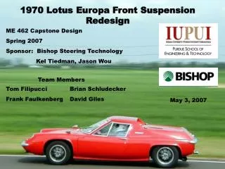
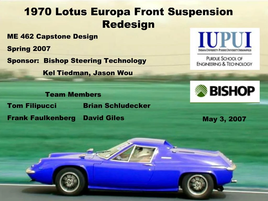
2. Project Background 1970 Lotus Europa
1470cc, 4-cylinder engine producing 78 hp
120 mph top speed
13-inch wheels
2-piece control arms
Stamped & welded
Bolt-on ball joints
Coil-over shock
& spring arrangement
3. Customer Requirements Maintain suspension geometry
Provide stable 200 mph ride
Maintain 5 inch ride height
Utilize 15 inch Audi wheels
Utilize current frame mounting points
Maintain wheel-to-wheel dimension
Attempt to utilize stock shock and spring size
Minimal bodywork modifications
4. Engineering Targets
5. Final Design
6. Final Design Upper Arm = 5.60 in
Lower Arm = 11.03 in
Scrub = 10 mm
Steering Axis = 16.5�
Rotor Clearance = 0.69 in
7. Design Animation
8. Design Animation
9. Design Evaluation Suspension Analysis
Four-bar Mechanism
10. Design Evaluation �Fourbar� Program � Norton
Evaluate each control arm length iteration
Rough wheel motion
�Four-bar Mechanism� - Matlab
Quantitative wheel motion
ProEngineer Mechanism output to Excel
�Camber Curve� - Matlab
Camber curve comparison
11. Design Evaluation Iteration Method
2 Iteration Sets
First Set � 11 possibilities
Manipulated Variables
Scrub radius
Steering axis
Second Set � 6 possibilities
Same Variables
Smaller scrub radii
Larger steering axes
12. Design Evaluation Case 5:
Steering Axis � 16.5�
Scrub radius � 10.0 mm
Upper arm � 5.60 in
Lower arm � 11.03 in
Case 1:
Steering Axis � 16.0�
Scrub radius � 11.0 mm
Upper arm � 5.70 in
Lower arm � 11.04 in
13. Design Evaluation
14. Design Evaluation
15. FEA Results
16. Final Evaluation
17. Conclusion & Recommendations Conclusion
Kinematic motion requirements met
Verified some physical packaging requirements
Recommendations
Further finalization of arm shapes
In-depth finite element analysis
Close examination of control arms and knuckle attachment
One team for knuckle/brake and suspension design
18. Questions?