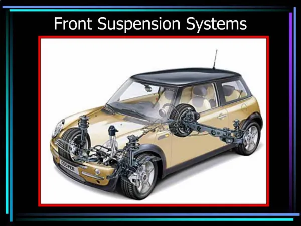
Front Suspension
Front Suspension. Greg Habiak , Nicole Simon, Joe Vuto. Bill of Materials. 2011 Yamaha Raptor 125 Steering Knuckle/Hub Assembly. Rod Ends at Steering Knuckle. Parameters from Trade Study. Camber = 10° Caster = 5° Kingpin Angle = 13° Scrub = 1.23 in.

Front Suspension
E N D
Presentation Transcript
Front Suspension Greg Habiak, Nicole Simon, Joe Vuto
Parameters from Trade Study • Camber = 10° • Caster = 5° • Kingpin Angle = 13° • Scrub = 1.23 in.
Parameters from 2D A-Arm Motion Analysis • Ride Height = 10.7 in. • Minimum Clearance = 4.8 in. • Total Travel of Tires = 11 in. • Total Travel of Rod Ends = 45.3° • Track Width = 53.625 in.
Steering Parameters • Max Turning Angle of Tire = 36.4° • Rack and Pinion has 4 in. total travel • Minimum Turning Radius = tan(90°- 36.4°)*WB • Wheelbase = 61.79 in. • Minimum Turning Radius = 7.0 ft • Percent Ackermann = 0%
Parameters from Force Analysis • Shock Force at Full Compression = (271.774, -387.566, 83.466) lbf • Calculated assuming car landed on only two wheels (275 lbf acting on one tire) and shocks are fully compressed. • Maximum Centripetal Force = (-112.5, 0, 0) lbf • Assuming 1g for centripetal force experienced on car, with 50% acting on the front, 90% of that acting on one tire, and 50% of that acting on one a-arm. • Maximum Braking Force on Bottom A-Arm = (0, 0, -520.3) lbf • Calculated from 1040.625 maximum braking torque according to Brakes • Maximum Braking Force on Top A-Arm = (0, 0, -416.3)lbf • Where X is normal to the right side of the toe box, Y is normal to ground, and Z is normal to the front of the car.
Top A-Arm FEAwith heat treated 6061 Max Stress = 11.72 ksi Safety Factor = 2.56 Max Deflection = 0.023 in.
Bottom A-Arm FEAwith heat treated 6061 Max Stress = 9.27 ksi Safety Factor = 3.23 Max Deflection = 0.035 in.
Bottom A-Arm FEAwithout heat treatment > 8 ksi Surpasses the yield strength of 6061-O, but not the tensile strength Not accurate because the majority of the a-arms will be stronger material and able to take the applied force. Plan to build aluminum a-arms to test and steel a-arms as backup Steel a-arms add 4.654 lbs to FS weight. Brings total weight to 86 lbs.