Download
1 / 19
190 likes | 362 Views
Advanced Energy Vehicle. System Analysis 3 Reference: AEV Lab Manual System Analysis 3 Lab Procedure Guidelines. FINAL DESIGN. AEV Project Objective (Problem Definition). Initial Concepts (Brainstorming). experimental Research. (Programming). (System Analysis). PT 1 PT 2 PT 3

E N D
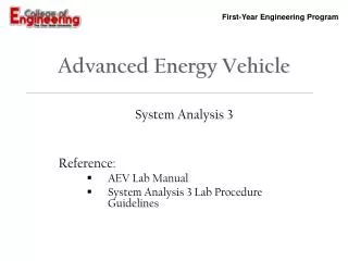
Advanced Energy Vehicle System Analysis 3 Reference: AEV Lab Manual System Analysis 3Lab Procedure Guidelines
FINAL DESIGN AEV Project Objective (Problem Definition) Initial Concepts (Brainstorming) experimental Research (Programming) (System Analysis) PT 1 PT 2 PT 3 PT 4 Present AEV Design
Lab Objectives • The objectives of this lab are: • Become familiar with propulsion system efficiency. • Become familiar with the wind tunnel testing equipment. • Conduct wind tunnel testing on electric motor and propeller. • Conduct analysis of wind tunnel testing results. • Update propulsion efficiency performance characteristics (Relates to System Analysis 2).
Lab Goals AEV Lab Manual – System Analysis 3 • The goal of this lab is to determine how efficient the propulsion system is by • Controlling the input power supplied to the motor • Measuring the power output generated by the electric motor and propeller
System Analysis 3 Equipment AEV Lab Manual – System Analysis 3 Power Supply (Motor Controller) Wind Tunnel Velocity Display Thrust Stand & Scale Wind Tunnel Speed Controller
System Analysis 3 Equipment AEV Lab Manual – System Analysis 3 • Power Supply (Motor Controller) Motor connections & On/Off Switch. Switching the ground & positive connections changes the direction the propeller rotates. Voltage Control & Display. Will set 0-6 volts in .5 volt increments. CurrentControl & Display. Kept constant.
System Analysis 3 Equipment AEV Lab Manual – System Analysis 3 • Wind Tunnel Velocity Display Wind Tunnel Velocity Display. Only concerned with velocity reading. Reset Button. If velocity ~= 0, press the reset button to recalibrate.
System Analysis 3 Equipment AEV Lab Manual – System Analysis 3 • Thrust Stand & Scale Motor Set Screw Thrust Stand Disengaged (Not resting on the scale) Thrust Stand Engaged (Resting on scale) Scale
Thrust Scale AEV Lab Manual – System Analysis 3 • Thrust Scale Thrust Reading Make sure before you “engage” the thrust stand, that the thrust scale reads zero. If it is not reading zero then hit the “Zero/TARE” button On/Off Button Zero/Tare Button
System Analysis 3 Equipment AEV Lab Manual – System Analysis 3 • Wind Tunnel Speed Controller Wind Tunnel Speed Controller. Scale 0 – 10 Typically ~6 On/Off Switch
Wind Tunnel Analysis AEV Lab Manual – System Analysis 3 • Recall that the propulsion efficiency of the AEV is a function of velocity and propeller RPM (or the non-dimensional propeller advance ratio parameter) • Therefore, we need to be able to control both AEV velocity and propeller RPM within a specified range in order to determine the efficiency characteristics of the propulsion system
Wind Tunnel Analysis AEV Lab Manual – System Analysis 3 • We are able to do this with Wind Tunnel Testing • We will use a wind tunnel to: • Set simulated AEV velocity (constant) • Range the propeller RPM by varying the voltage on the motor controller. • Note: RPM is a function of voltage of this lab. Provided in the AEV Lab Manual. • Our range is set from 0 to 6 volts.
Configuration Selection Thrust Line Thrust Line • Two type of motor configurations • Your team will want to decide the configuration you’re going to test based on your preliminary design. • Take careful notice: • Orientation of motor supply wiring • Propeller orientation on the electric motor Pusher Configuration Puller (Tractor) Configuration
Proper Propeller Orientation Visual Confirmation of Propeller Orientation Counter-clockwise rotation Propeller number designation • For either Puller or Pusher Configuration - • When looking at the propeller (i.e. AEV) from the front (strain gauge base): • The propeller number designation should be visible • The propeller should be rotating counter-clockwise
Wind Tunnel Analysis AEV Lab Manual – System Analysis 3 • You will be setting the power supplied (input) using the motor controller and recording the voltage and current supplied to the motor. • Remember: • Where V is the voltage and I is current
Wind Tunnel Analysis AEV Lab Manual – System Analysis 3 • You will be using the thrust stand to measure the thrust of the propulsion system • Power Available • (output) can be • calculated using the • wind tunnel velocity • and thrust readings. + Thrust Direction Scale Reading
Wind Tunnel Analysis AEV Lab Manual – System Analysis 3 • Once testing is complete and the power supplied (input) and power available (output) is calculated, you can determine the propulsion system efficiency for your AEV motor and props • The efficiency can then be related to the advance ratio, J, from the known wind tunnel velocity set and the variable RPM
Wind Tunnel Testing Outline AEV Lab Manual – System Analysis 3 Perform Wind Tunnel Testing. Record: Voltage Current Thrust In 0.5 volt increments Perform Wind Tunnel Analysis. Compute: RPM J
System Analysis 3 Lab Lab Activity • Follow AEV Lab Manual and Lab Procedure Guidelines • Team: • Print two hard copies of the Wind Tunnel Testing Results spreadsheet (EP-3030 & EP-3020) • Select propeller and motor configuration • Conduct wind tunnel tests through voltage range (6V – 0V) • Individual: • Record data into the Wind Tunnel Testing Results spreadsheet • Analyze results