Download
1 / 15
150 likes | 313 Views
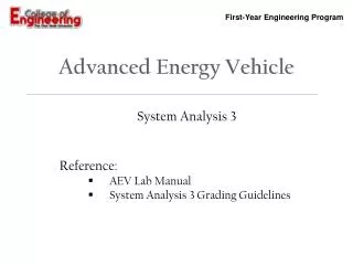
Advanced Energy Vehicle. System Analysis 3 Reference: AEV Lab Manual System Analysis 3 Grading Guidelines. FINAL DESIGN. AEV Project Objective (Problem Definition). Initial Concepts (Brainstorming). experimental Research. (Programming). (System Analysis). PT 1 PT 2 PT 3 PT 4.

E N D
Advanced Energy Vehicle System Analysis 3 Reference: AEV Lab Manual System Analysis 3Grading Guidelines
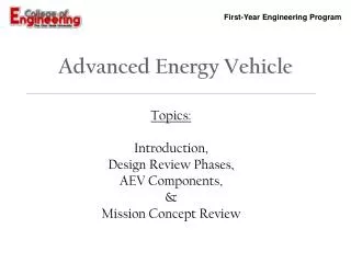
FINAL DESIGN AEV Project Objective (Problem Definition) Initial Concepts (Brainstorming) experimental Research (Programming) (System Analysis) PT 1 PT 2 PT 3 PT 4 Present AEV Design
Lab Objectives • The objectives of this lab are: • Become familiar with propulsion system efficiency. • Become familiar with the wind tunnel and thrust stand equipment. • Conduct wind tunnel testing on electric motor and propeller. • Conduct analysis of wind tunnel testing results. • Update propulsion efficiency performance characteristics.
Equipment AEV User Manual – System Analysis 3 Power Supply (Motor Controller) Thrust Stand Wind Tunnel Speed Controller Thrust Stand Data Acquisition (DAQ) System
Lab Goal AEV User Manual – System Analysis 3 • The goal is to determine how efficient the propulsion system is by • Setting the input power supplied to the motor, and • Measuring the power output generated by the electric motor and propeller
AEV Energy Analysis AEV User Manual – System Analysis 3 • Recall that the propulsion efficiency of the AEV velocity and propeller RPM (or the non-dimensional propeller advance ratio parameter) • Therefore, we need to be able to control both AEV velocity and propeller RPM throughout a range in order to determine the efficiency characteristics of the propulsion system! • How can we do this!?!
AEV Energy Analysis AEV User Manual – System Analysis 3 • Wind Tunnel! • We will use a wind tunnel to set the simulated AEV velocity and range the propeller RPM!
AEV Energy Analysis AEV User Manual – System Analysis 3 • Make sure to follow the Lab Manual carefully to set up the proper configuration for your AEV • i.e. Puller (Tractor) or Pusher configuration • See next slides
Configuration Selection Puller (Tractor) Configuration Pusher Configuration • In the lab procedure, take careful notice to; • propeller orientation on the electric motor • motor power supply wiring
Proper Propeller Orientation Visual Confirmation of Propeller Orientation Counter-clockwise rotation Propeller number designation • For either Puller or Pusher Configuration - • When looking at the propeller (i.e. AEV) from the front (strain gauge base): • The propeller number designation should be visible • The propeller should be rotating counter-clockwise
AEV Energy Analysis AEV User Manual – System Analysis 3 • You will be setting the power supplied (input) using the power supply and recording the voltage and current supplied to the motor. • Where V is the voltage
AEV Energy Analysis AEV User Manual – System Analysis 3 • You will be using the thrust stand to measure the thrust of the propulsion system • And wind tunnel • velocity to • calculate • Power Available • (output) Motor Set Screw Motor Mount + Thrust Direction Strain Gauge
AEV Energy Analysis AEV User Manual – System Analysis 3 • Once testing is complete and the power supplied and available is recorded and calculated, you can determine the propulsion system efficiency for your AEV motor and props
AEV Energy Analysis AEV User Manual – System Analysis 3 • The efficiency can be related to the non-dimensional parameter from the known wind tunnel velocity set and the variable RPM • The RPM for the tunnel testing, as function of the supplied voltage, can be determined with the following trends:
System Analysis 3 Lab Lab Activity • Follow AEV Lab Manual and Lab Procedure Guidelines • Team: • Print hard copy of the Wind Tunnel Testing Results spreadsheet • Select propeller and motor configuration • Conduct wind tunnel tests through voltage range (2.5V – 6V) • Individual: • Record data into the Wind Tunnel Testing Results spreadsheet • Analyze results