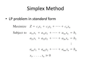
Simplex comber ringframe
Presentation about 'Simplex comber ringframe'

Simplex comber ringframe
E N D
Presentation Transcript
Southeast University Southeast University Department Of Textile Engineering Department Of Textile Engineering I/A 251,252 Tejgaon Dhaka Banglade I/A 251,252 Tejgaon Dhaka Bangladesh sh
Function/objectives/What it Function/objectives/What it does? does? • The chief function of roving frame is the attenuation of sliver. • Insertion of protective twist in order to hold the fine strand of sliver. • Winding of roving into a package that can be transported, sorted, donned on ring spinning machine.
Limitations/Draw backs Limitations/Draw backs • Complicated machine • Liable to faults • Causes defects • Add to production costs • Roving is sensitive in both winding & unwinding Complicated winding operations • Spindle & flyer • A cone drive transmission • A differentiate gear • Builder motion. •
Necessity of Roving Frame Necessity of Roving Frame • There are two principle reason: – First reason is to apply drafting. – Sliver is thick, untwisted strand that tends to be hairy and to create fly. There fore, if we directly want to produce yarn from sliver by discarding simplex, we need 300 to 500 draft to do so. But the fine twisted roving is significantly better suited to this purpose. – Second reason is related with transportation and space limitation on ring frame. – Draw frame “can” is the worst conceivable mode of transportation and presentation of feed material.
Operating region of Roving frame Operating region of Roving frame The creel The drafting arrangement Roller drafting system The apron Applying pressure to the top roller. The condenser The spacer Winding of bobbin Package build Bobbin drive Cone drive transmission The lifter motion The builder motion Spindle & flyer Imparting twist Spindle Flyer Design of flyer Pressure arm
Drafting arrangement of roving frame Drafting arrangement of roving frame • Roller Drafting system – Conventional roller drafting system: – 4 over 4 without apron. – Modern Roller drafting system: – 3 over 3 drafting system with double apron (Lakshmi Rieter FS185P) – 4 over 4 drafting system with double apron (SKF PK 1600)
SKF PK-1600 drafting system SKF PK-1600 drafting system • Draft range: Total draft 5 to 20 • Total draft is distributed in each zone as follows: – Back zone: Break draft is applicable in here. Amount of break draft is depends upon material. Material Break Draft Sliver Coarse 1.5-1.4 Sliver Medium 1.4-1.3 Sliver Fine 1.3-1.2 Sliver MMF 1.2-1.1
• Middle zone: – Less amount draft is applicable in here. – Condenser is used in middle zone to condense sheet like sliver. • Front zone: – Maximum amount of draft is applicable in here. Apron is used in this zone.
• Roller type: – Top rollers are synthetic rubber coated – Bottom rollers are made of steel – Front, 3rd and back rollers (bottom) are spiral fluted. – 2nd roller has granulated pin.
• Roller dia: Roller Front roller 2nd roller 3rd roller Back roller Top roller 28 mm 25 mm 28 mm 28 mm Bottom roller 30-32 mm 25-27 mm 30-32 mm 30-32 mm
The Apron: The upper aprons are short and made either of leather or more commonly of synthetic rubbers. They have a thickness of about 1 mm and are held by tensioning device. The lower aprons are longer and usually made of leather. They run over the guide bar, usually known as nose bar, to position close to the delivery roller. Function: The aprons co-operated with each other t guide and transports the fibers during drafting and they exert a very significant influence on the drafting operations.
Applying pressure to the top roller • The top roller must be pressed with relatively high force against the lower rollers to ensure the guidance of fiber. • Pressure are in the range of 100 to 250 N per roller which may vary as per raw material and its volume. • Pressure is applied by spring pressure, pneumatic weighting, magnetic weighting.
Condenser Condenser Feature: •Condensers are mounted on a reciprocating bar behind the drafting arrangement. •The second condenser is provided in break draft field. •And the 3rd one is located in main draft field. Function: •Spreading sliver masses are condensed to improve evenness and lead to drafting zone. Advantage: •Reduce the high fly level and hairiness of roving.
Spacer Spacer • As the top apron are forced by spring pressure against the lower apron, the arrangement of this apron should permit precise adoption of minimum distance to fibre volume. In order to be able to maintain this minimum distance, spacer are replace ably inserted between the nose bar of the lower apron and the cradle edge of top apron. Spacer size is 4 to 7 mm in accordance with roving hank.
Imparting Twist Imparting Twist
The flyer The flyer • Flyer is used to impart twist • Flyer has two legs, one with hollow path or slot and pressure arm another for balancing the flyer while rotating. • Flyer is placed on spindle, it gets motion by gearing. • Flyer speed has direct influence on production. • Flyer can be varying in sizes which are specified in inch. For example, 12”X 5.5”, 12”X6” and 14”X6”. First no. indicate maximum height and second no. indicate maximum dia of wound package.
Pressure Arm Pressure Arm • A steel yoke attached to the lower end of hollow flyer leg is called pressure arm. • The roving is wrapped 2 or 3 times around the yoke. • The no. of turn determine the roving tension. For higher tension, a hard compact package is obtained and if it is too high false draft or roving breakage can be caused. • Therefore, the no. of wrap depends upon material and twist level.
Winding Principle Winding Principle • Bobbin leading principle (For cotton spinning) • Flyer leading principle (For jute spinning)
Bobbin leading Principle Bobbin leading Principle • Bobbin speed is higher than flyer speed at all point of winding. • The winding on speed is constant throughout the process. • With the increase of bobbin dia, bobbin speed must be decreased. • The variation of bobbin speed with the increase of bobbin dia must be constant. • Less tension on roving. Bobbin Speed Empty Bobbin Full Bobbin RPM Flyer Speed d
Flyer Leading Principle Flyer Leading Principle • Flyer speed is higher than bobbin speed at all point of winding. • The winding on speed is constant throughout the process. • With the increase of bobbin dia, bobbin speed must be increased. • The variation of bobbin speed with the increase of bobbin dia must be constant. • Higher tension on roving. Flyer Speed Full Bobbin Empty Bobbin Bobbin Speed
Recent Development of Speed Frame Recent Development of Speed Frame 1. Improved drafting system: Modern drafting system like SKF PK 1600, SKF PK 5000 etc give more controlling to fibre and they able to import 8 to 20 draft on sliver. 2. Higher flyer speed: Modern flyer speed is more than 1000 rpm where as the convention flyer reaches maximum 600 rpm. 3. Plastic flyer: lighter in weight and less power consumption in result. 4. Flyer driving from top: Modern flyers are top mounted and having no spindle which in turns facilitate following issues: Auto doffing operation Reduced flyer leg spreading Higher flyer speed 5. Inching motion: It initiates flyer turning slowly for piecing if the end breaks. And also ensures less tension on roving while the machine starts.
6. Auto stop motion: Various auto stop motions are initiates to reduce waste and increase efficiency: Sliver stop motion, Roving stop motion, Creel stop motion, full bobbin stop motion, Doffing stop motion. 7. Pre determine set length: Machine stops automatically after a predetermined length of roving is wound on bobbin. 8. Monitoring system: Modern speed frame includes data monitoring system by direct reading of :production, efficiency, speed of flyer, stoppage time, quality monitoring and package built. 9. Auto doffing: Like some ring spinning machine, simplex machine manufacturers offer the machine having automatic doffing system where full bobbins are replaced by empty bobbin without any help of worker. 10. Automatic tension controller: it determines the tension on roving continuously and send data to inverter to adjust its speed.
Faults in speed frame Faults in speed frame: • Irregular roving • Irregular draft • Top roller dia variation • Pressure variation. • Rough surface of apron • Improper roller setting • Roving Breakage: •Irregular roving •Tension variation •Variation of pressure on top roller •Unequal tapering: •Wrong angle of poker rod •Different lifting and lowering distance due to faulty builder motion •Soft bobbin: •Winding on speed is less than front roller delivery •Less tension on roving during winding •Less coil/inch (if top rail speed is too high it results excessive spacing between adjacent coil.) • Sloughing off: •Improper taper end •Faulty taper wheel •Roller lapping: •Stickiness formation on roller •Wet roller surface •Excessive dry roller surface •Dust deposit on roller. •Dirty roving bobbin: •Excessive oiling on machine parts •Insufficient machine cleaning •Cracked bobbin and careless handling
Comber Comber
Function Function Remove short fibre below a preselected length and there by reduce length variation in the cotton mixing. Improve fibre parallelization and fibre to fibre separation and minimize the fibre entanglement and disorientation. Remove neps and foreign matter form the cotton.
Excellence of fiber quality by Excellence of fiber quality by combing combing:
Parameter/ Specification of Parameter/ Specification of comber comber • Feed/nips 6-8 mm • Nips/min 220-600 • Lap weight 800-1200 grs/yd • Noil % 10-25% • Efficiency 90-95%
Line diagram of comber Line diagram of comber Top nipper Top comb Detaching roller Feed Roller Lap Feed Plate Cylin der Bottom nipper Delivery roller
Machine Setting Depends on Noil Extraction% Machine Setting Depends on Noil Extraction% • Feed Distance • Type of feed • Detachment setting • Point density on top combs • Piecing
Feed Distance: Feed Distance: – Feed distance means feed per nip. – Feed distance has a influence on • Noil • Quality of combing operation • Production rate. High feed distance increase the production rate but causes deterioration in quality. Feed distance approximately correlated with fibre length.
Type of feed Type of feed • Forward feed has been chosen for higher production rate when quality requirement is not rigorous with a noil % of 5- 12 %. • Backward feed has to use for higher quality requirement with a noil % of 12 to 25%
The detachment setting The detachment setting • This is the distance between the bite of the nippers and the nip line of detaching rollers. • Higher detachment setting bring the high elimination of noil • The detachment setting normally lies in the range of 15 to 25 mm.
The no. of points on comb The no. of points on comb • Point density and the fineness of needle have to be adopted to the material. • The needle of top combs have a flattened X-section and are formed with a bend. • The point density is 23-32 needles per cm. • Fewer needles are used for higher production with lower waste elimination.
Top comb Penetration Top comb Penetration • Higher top comb penetration results higher elimination of noil. • Lowering the top comb by 0.5mm is followed an increase in noil of about 2%. • The main improvement is seen in the elimination of neps. • Over deep penetration may disturb fibre movement during piecing. This results in deterioration of quality%.
Piecing Piecing • After combing of the fringe protruding from nippers, the detaching roller draws some of the combed feedstock out of the sheet. • By means of this piecing operation, the roller have to lay these strips of web on top of each other, so that first a coherent web and finally a endless ribbon is obtained. • This sliver produced in this way has a wave like structure, it exhibits periodic variation. • By using correct machine setting, it is possible to lay the fringe on each other that unevenness in successive fringes partly cancels out.
Parameter influence the combing operation • Raw material – Fibre type – Fibre length – Uniformity of fibre length – Fibre stiffness – Moisture content • Material Preparation – Parallelization of fibers in the sheet. – Sheet thickness – Sheet Evenness – Orientation of hooks in the sliver.
Factors associated with M/C Factors associated with M/C • Condition of machine • Condition of comb • Speed • Operation of combs • Types of sliver forming elements • Accuracy of the setting • Drafting arrangement.
Effect of combing on staple diagram Effect of combing on staple diagram Before combing After combing Noil%
Relationship between noil% and improvement of yarn quality A= Improvement of Yarn Quality in % B= Noil elimination in % a= Yarn strength b=Yarn evenness c= Yarn imperfection
Sequence of combing cycle Sequence of combing cycle a. Lap feeding by feed roller: The lap is fed into the machine between the feed roller and feed plate. The feed roller moves and material passes forward. b. Lap nipping by the nipper: the nipper moves downwards towards the feed plate, so that the fibres are clamped between them. Cylinder is then ready for combing.
c. Combing by cylinder: The fibres protruding from the lap beyond the nipping point of the two plates, are combed by the passage of rows of needles fastened to a cylinder which revolves and carries away the short fibres, neps and other impurities. d. Nipper opening and forwarding: the nipper open again and the material combed by the cylinder moves towards the detaching roller.
e. movement: when the top nipper reach upwards, the detaching roller have returned parts of previously drawn off stock by means of reverse rotation. Detaching roller backward f. Combing by top comb: the top comb penetrate its single rows of needles in to the fibre fringe. Thus top comb perform the combing operation on the upper side of fringe.
g. Detaching roller forward movement: The detaching roller begin to rotate in the forward direction again and draw the clamped fibres out of the sheet which is held first by the feed roller. h. Waste extraction by brush
Ring Frame Ring Frame
Ring Spinning System Ring Spinning System (Conventional but competitive) • Ring frame exhibits significant advantage in comparison with new spinning system: – It is universally applicable; ie. Any material can be spun to any required fineness. – It delivers yarn with optimal characteristics, especially with regard to structure and strength. – It is uncomplicated and easy to operate. – The know-how for operation of machine is well established and accessible to everyone. – It is flexible as regards to its quantities. (Blend & lot size)
FUNCTIONS/ OBJECTIVES FUNCTIONS/ OBJECTIVES • Attenuation of roving until the required fineness is achieved. • To impact strength to fibre strand by twisting it. • To wind up the resulting yarn in a form that it will suitable for storage, transportation and further processing.
Operating Principle: Operating Principle: •The roving bobbins (1) are inserted in holders (3) on the creel. Guide bars (4) guide the rovings (2) into the drafting system (5), where they are drawn to their final count. The drafting system is at an angle of 45-60° and is one of the most important units on the machine, since it exerts a very considerable influence on the uniformity of the yarn in particular. •After the resulting thin ribbon of fibers (6) leaves the delivery roller, the twist necessary for imparting strength is provided by spindle (8) rotating at high speed. In the process each rotation of the traveler on the spinning ring (10) produces a twist in the yarn. Ring traveler (9) is also necessary for taking up this yarn onto a tube mounted on the spindle. This traveler - a remnant of the flyer on the roving frame - moves on a guide rail around the spindle, the so-called ring (10). The ring traveler has no drive of its own, it is dragged with spindle (8) via the yarn attached to it. The rotation of the ring traveler lags somewhat behind that of the spindle due to the relatively high friction of the ring traveler on the ring and the atmospheric resistance of the traveler and the thread balloon between yarn guide eyelet (7) and traveler (9).