Download
1 / 12
120 likes | 215 Views
Explore weld evaluation for power supply loads in NSTX project, using fracture mechanics analysis to assess crack growth and stress intensity factors. An experimental investigation of fatigue crack growth in stainless steel 304L is discussed.

E N D
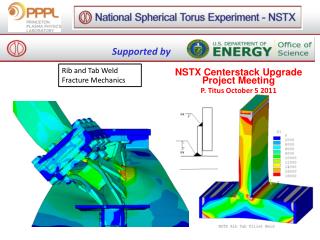
Supported by Rib and Tab Weld Fracture Mechanics NSTX Centerstack Upgrade Project Meeting P. Titus October 5 2011
30 degree Cyclic Sym – OOP Loads from Han Multiplied by 12/10 Gap Elements (52 Point to Point) Tab Models are reflected - Both sides mirror images of the other - Welded only on top and Bottom with gaps/contact elements between the tab and rib
Rib Tab Weld Evaluation forWorst Case Power Supply Loads Actual Weld Detail Assume bevel backed by a fillet is like a full penetration. Tab weld Stresses all appear less than 96 MPa
Tensile Side 73MPa away from the weld Or 10.5 ksi Compressive Side Crack is Closed on the Tensile Side
An Experimental Investigation of Fatigue Crack Growth of Stainless Steel 304L S. Kalnaus,F.Fan, Y Jiang, A.K. Vasudevan University of Nevada and Office of Naval Research , International Journal of Fatigue, Volume 31, Issue 5, May 2009 [14]
The root of the weld isassumed to be a crack geometry and the SIF is computed in ANSYS.
.088 in Crack Depth No Lateral Fixity at top of Tab **** CALCULATE MIXED-MODE STRESS INTENSITY FACTORS **** ASSUME PLANE STRESS CONDITIONS ASSUME A FULL-CRACK MODEL (USE 5 NODES) EXTRAPOLATION PATH IS DEFINED BY NODES: 10661 10649 10663 10681 10693 WITH NODE 10661 AS THE CRACK-TIP NODE USE MATERIAL PROPERTIES FOR MATERIAL NUMBER 1 EX = 0.29000E+08 NUXY = 0.30000 AT TEMP = 0.0000 **** KI = 12979. , KII = 5075.6 , KIII = 1860.8 ****
.088 in Crack Depth Lateral Fixity at top of Tab Added **** CALCULATE MIXED-MODE STRESS INTENSITY FACTORS **** ASSUME PLANE STRESS CONDITIONS ASSUME A FULL-CRACK MODEL (USE 5 NODES) EXTRAPOLATION PATH IS DEFINED BY NODES: 10661 10681 10693 10649 10663 WITH NODE 10661 AS THE CRACK-TIP NODE USE MATERIAL PROPERTIES FOR MATERIAL NUMBER 1 EX = 0.29000E+08 NUXY = 0.30000 AT TEMP = 0.0000 **** KI = 7305.0 , KII = 4191.5 , KIII = 1589.9 ****
.088 in Crack Depth .125 in Crack Depth Lateral Fixity at top of Tab Added **** CALCULATE MIXED-MODE STRESS INTENSITY FACTORS **** ASSUME PLANE STRESS CONDITIONS ASSUME A FULL-CRACK MODEL (USE 5 NODES) EXTRAPOLATION PATH IS DEFINED BY NODES: 10661 10681 10693 10649 10663 WITH NODE 10661 AS THE CRACK-TIP NODE USE MATERIAL PROPERTIES FOR MATERIAL NUMBER 1 EX = 0.29000E+08 NUXY = 0.30000 AT TEMP = 0.0000 **** KI = 7936.9 , KII = 4341.6 , KIII = 1687.4 ****
! Simple da/dn integral for 304 Stainless Steel let t=.5*.707/39.37 let ainit=.125/39.37 let m=2.95 let c=5.43e-12 let fractTough=100 let deltak= 7305*6895/1e6/39.37^.5 let a=ainit let abreak=ainit+t let counter = 0 !for i= 1 to 10000 do !deltak is linear in crack length let delk=deltak/ainit*a !assume the delta k scales with the orig thick/remaining thickness let delk=delk*(t+ainit)/(t+ainit-a) let i=i+1 let counter=counter+1 let dadn=c*delK^m let a=a+dadn if counter = 100 then print i;",";delk;","; a let counter = 0 end if if a>abreak or delk>fractTough then exit do !next i loop print "Cracked Through" end
Crack Size in meters vs. Cycles Delta K in Mpa root m vs. Cycles