Download
1 / 28
280 likes | 683 Views
Introduction to 85108A Pulsed Network Analyzers. Pengcheng Jia Dec 13, 2001. Outline. What is measurement? What is 85108 Pulsed Network Analyzer? What are the Connectors & Cables? What are the Calibration Kits? What is Non-Insertable Calibration? How to do Pulsed Measurement?

E N D
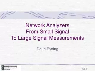
Introduction to 85108A Pulsed Network Analyzers Pengcheng Jia Dec 13, 2001
Outline • What is measurement? • What is 85108 Pulsed Network Analyzer? • What are the Connectors & Cables? • What are the Calibration Kits? • What is Non-Insertable Calibration? • How to do Pulsed Measurement? • How to Control by Computer?
What is measurement • Define Measurement: f, P, T, expected values and tolerance. • Define System Configuration • Configure Hardware: User setting, Gauging, Always use ESD Protection • Check Hardware: DUT, Cables, Connectors • Calibrate • Verify • Measure • Analyze and Archive
System Cabling Diagram LO source: 10M-20 G RF source: 10M-50 G Test Set: 1-50 GHz Test Set works from 1-50 GHz in 2 Bands: 1-20 GHz Use directly LO source. 6-50 GHz Use third harmonic of LO source.
50 MHz to 40 GHz • 100 dB of dynamic range • Excellent measurement accuracy • Two measurement channels • Four display channels Simplified NA - 8722D
Avoid Large Time Delay of DUT Frequency Sweep f Step Mode: 85108A 200 ms t f Ramp Mode: 8722D t DUT 3KHz BW =10 ns Original Ramped 8722D with 3K IF BW f 4KHz
Pulse Meas.- Freq Domain • Point-in-Pulse • Freq Domain Meas. • Use 1.5M Broadband IF filter (Normal meas. use 10K IF filter) • Adjustable Duty Cycle • Default: 10% • Adjustable Pulse Width • Default: 10 ms, min 1us • Trigger time: 5ms from 0
Pulse Meas.-Time Domain • Display Time Domain Pulse Profile • Choose Pulse Profile in Domain menu • Measure only at a single frequency
High Power Meas. +43 dBm +43 dBm +17 dBm +17 dBm Never Exceed the Power Limitation on the Test Port Port1 & Port2: +43 dBm RF Input Port: +17 dBm
Connectors for NA PSC: Precision Slotless Connector
Cables for NA • Cables (only following cables can be used for NA): • Semi-Rigid with K connectors • Flexible—Thin Jacket with K connectors (Blue, from Gore) • Flexible—Thick Jacket with 2.4 mm connectors (Black, from Agilent) • Connectors on Port 1 & 2 is 2.4 mm • 2.4 to 2.9 (K) adaptors are put to mate with K connector cables, Never Remove Them • Always Keep Connects & Adaptors Clean • Treat Them Gentle and Put Back to Box
Cautions: • Select Correct Cal Kit and Load Calibration Constants before Calibration • Never Remove a Calibration Standard from the Box or Use for Any Purpose Other Than Calibration • Never Drop the Standards to Ground • Always Use Special Wrench Correctly • Put the Cal Kits Back to Cabinet after Use • Report Any Discrepancy
Load Configuration Disk • Load the Test Set Configuration Disk for 85110A with H60/61 option (Disks are stored in Drawers, never remove them) • Disk->Storage is Internal • Load->More->Machine Dump • MD_1_20_NP, 1-20 GHz, Non-Pulsed MD_1_20_PL, 1-20 GHz, Pulsed MD_6_50_NP, 6-50 GHz, Non-Pulsed MD_6_50_NP, 6-50 GHz, Pulsed
Calibration Procedure • Press Cal menu • Choose Calibration Kit, if not installed in equipment, load the cal constant from disk • Choose in the Calibration Menu • LRM for on-wafer Calibration, Full 2-port for cable calibration • Follow instruction, connect standards and measure • Save calibration data • You will see “Correction On”
Swap Equal Adaptors Swap Equal Between-Series Adaptors Swap Equal In-Family Adaptors
Adaptor Removal • Calibration with adaptor on Port 2, save as Cal Set 1 • Calibration with adaptor on Port 1, save as Cal Set 1 • Modify Cal Set->Adaptor Removal • Refer the additional document for more details • More calibration methods are included in that file
Calibration with On-Wafer Kit • Use WinCal on Controller-Dizzy • Calibration Constant is set in program • Choose LRM, since short is not good • LRRM is recommended for more accuracy
How to do Pulsed Meas.(1) • Frequency Domain (Point-in-Pulse) • Domain->Frequency • System->More->Pulse Config->Detector: • Wide BW • Select Maximum Points • Calibration • System->More-> Pulse Config-> High or Low • Set Pulse Width, Duty Cycle • Stimulus->More->Trigger Mode->Trigger Delay • Measure
How to do Pulsed Meas.(2) • Pulse Profile Domain - Single Frequency • Domain->Frequency • Stimulus->Step mode & Start->Set desired frequency • Domain->Pulse Profile • Select Maximum Points • Calibration • Measure • Repeat for Next Frequency
How to do Pulsed Meas.(3) • Pulse Profile Domain – Frequency List • Cal->Correction off • Domain->Frequency • System->More->Pulse Config->Detector: Wide BW • Stimulus->More->Edit List • Add->Start->3 G/n, Number of Points->51x1->Done • Add->Start->4 G/n x1->Done • Add->Start->5 G/n x1->Done • Done Frequency List, and Proceed with Calibration
How to do Pulsed Meas.(4) • Using Frequency List – Continue: • When begin to Measure: • Domain-> Pulse Profile • Stimulus->Frequency List->Single Segement • The last selected segment will be active and ready for measurement • Calibration will be effective for each frequency point • Set Pulse Polarity, Pulse Width and Duty cycle if needed
Computer Control • 2 GPIB Connectors are on the back of 8510C • 1 for 85108 System bus (don’t touch) • 1 for computer controller (already connected) • Dizzy is the controller • Use WinCal for On-Wafer Calibration and S-Parameter Measurement • Choose the correct VNA first • Config->Option->VNA->8510 or 8722 • Use Labview Program for 85108 configuration