Download

1 / 11
110 likes | 282 Views
Pulsed power poster introduction. Cristián Fuentes. cafuente@cern.ch. 2008-2011 -> CERN DCDC converters group with F. Faccio and G. Blanchot. March 2012 -> Fellow for CLIC experiment. 19/09/2012. Outline. Vertex barrel detector at CLIC. Introduction to the challenges.

E N D
Pulsed power poster introduction Cristián Fuentes cafuente@cern.ch 2008-2011 -> CERN DCDC converters group with F. Faccio and G. Blanchot March 2012 -> Fellow for CLIC experiment 19/09/2012
Outline Vertex barrel detector at CLIC Introduction to the challenges Analog: Regulation and Material Budget constrains Proposed scheme + implementation Invitation to my poster
Vertex Barrel detector at CLIC Ladder: 24 CLICPIX ASICs of 1cm2 area
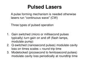
Why to power-pulse it? Values from CLICPIX design specifications Take advantage of the small duty cycle (or to power-pulse) to reduce the average power. ..but why is it important to reduce average power?
Challenges 1) Low losses:< 50 mW/cm2 in the sensor area, as the heat-removal solution is based on air-cooling to reduce mass. (must be shared among analog and digital electronics) 2) High magnetic Field: > 4 [Tesla] restricting the use of ferromagnetic material. 3) Material Budget: < 0.2%Xo for a detection layer, leaving less than 0.1%Xo for cooling and services. extra challenge for analog electronics 4) Regulation: within 5% (60 mV) on the ASIC during the acquisition time, expected to be close to 15 µs (CLICPIX specifications).
20 A CLICPIX ASICs Imax=20 A for half ladder Half Ladder ton~15µs tr and tf : few µs range ton~15µs Power in Power in Ladders recordar el numero de ladders por barrel Numero de pixels por asic Analog: Regulation and Material Budget constrains We power half a ladder, it means 12 chips of 1x1cm2 area Estudiar material budget y el significado de Xo o radiation length Power outside with regulated 1st ASIC 100µm PCB flex cable for regulation at the last ASIC. (2 copper layers) 14 times higher than target!! 35µm PCB flex cable. (2 copper layers) Still 5 times higher than target!!
Analog: Regulation and Material Budget constrains Half Ladder recordar el numero de ladders por barrel Numero de pixels por asic Lets imagine we want a really low mass cable: Lets say 8 µm PCB flex cable. (2 copper layers) Estudiar material budget y el significado de Xo o radiation length Still (but slightly) over the target!! Nevertheless, in order to compensate a so resistive cable (50mOhms) we may need local regulation and/or capacitor storage (remember: 20A required). Lets add 1 ceramic SMD 1206 capacitor per chip (12 ceramic cap in total) 5 times over target! Lets just add 1 ceramic SMD 1206 capacitor every four chips (3 cap in total) Still (but slightly) over the target!! NOTE: the material of the cable and capacitors must be added.
Proposed scheme + implementation So what can we use??? Aluminum flex cables: For the same resistance of a cable, aluminum has 4 times lower %Xo than copper. Example: For the same resistance than 35µm of copper. 0.49 vs 0.12-> 4 times better! Silicon capacitors: Silicon capacitors is another technology that helps to reduce Xo. We can find capacitors with a density of 25uF per cm2 in a thickness of 100µm. Example: For the same capacitance than 12 smd 1206 capacitors of 10µF. 0.5 vs 0.055-> almost 10 times better! NOTE: Silicon capacitors have higher ESR than ceramic capacitors. In the order of 100-400 mOhms
Proposed scheme + implementation The front end readout ASICs are now under development. In order to test the proposed pulsed-powered scheme, their behavior was emulated using a PCB.
Proposed scheme + implementation agregar los resultados 0.145%Xo With future work we expect to reduce it below 0.1%Xo
Invitation to the poster... So if you are interested in: -further details of the proposed power scheme -the currently obtained results -how they will be improve with future work -Share your knowledge and ideas with me -Or just to make my thursday afternoon funnier :) you are most welcome to see my poster tomorrow, located at B10.