Download
1 / 164
1.64k likes | 1.7k Views
Explore VHDL history, operators, statements, subprograms, and advanced topics. Understand hardware/software co-design and VHDL organization.

E N D
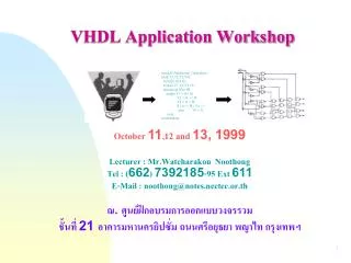
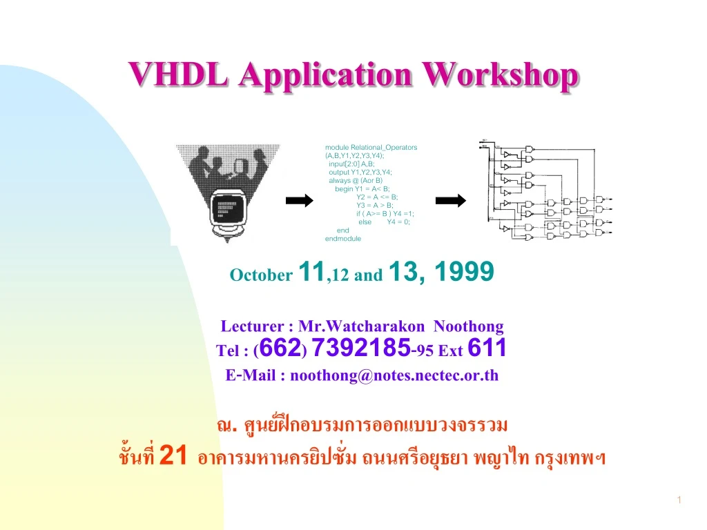
VHDL Application Workshop module Relational_Operators (A,B,Y1,Y2,Y3,Y4); input[2:0] A,B; output Y1,Y2,Y3,Y4; always @ (Aor B) begin Y1 = A< B; Y2 = A <= B; Y3 = A > B; if ( A>= B ) Y4 =1; else Y4 = 0; end endmodule October 11,12 and 13, 1999 Lecturer : Mr.Watcharakon Noothong Tel : (662) 7392185-95 Ext 611 E-Mail : noothong@notes.nectec.or.th ณ. ศูนย์ฝึกอบรมการออกแบบวงจรรวม ชั้นที่ 21 อาคารมหานครยิปซั่ม ถนนศรีอยุธยา พญาไท กรุงเทพฯ
Course Outline Day 1 1. Introduction and Overview - History, Limitation - Electronic system design - Levels of Abstraction 2. VHDL Objects - Entity, Architecture - Component, Package - Process, Configuration 3. Signal and Datatypes - Concept of a types - Standard data types - Scalar and array literals - IEEE Standard logic types 4. Object Declarations - Constant declaration - Signal declaration - Alias declaration - Variable declaration Day 2 5. VHDL Operators - Logical Operators - Relational Operators - Concatenation Operator - Arithmetic Operators 6. Sequential Statements - Process Statement - IF Statements - CASE Statement - LOOP Statements - WAIT Statements 7. Concurrent Statements - Condition signal assignments - Selected signal assignments - BLOCK/Guards Statement 8. Subprogram - Functions - Procedures Day 3 9. Advanced Topics - Advanced types - Overloading - RTL Styles 10. Testbench Coding Styles - Testbench configuration - Stimulus styles - Assertion - TextIO 11. VHDL & Logic Synthesis - Basic design methodology - Multiplexer, Encoder, Decoder - Tri-State, Bidirectional buffers - ALU (Arithmetic Logic Unit) - Finite State machine - Latch, Asynchronous Flip-Flop & Synchronous Flip-Flop
VHSIC (Very High Speed Integrated Circuit) Hardware Description Language • Modelling DIGITAL Electronic Systems • Both Concurrent and Sequential statements What is VHDL ?
VHDL History • Department of Defense (DoD) developed in 1981 • IEEE 1076-1987 Standard (VHDL’87) • IEEE 1076-1993 Standard (VHDL’93)
Hardware Description Language (HDL) The VHDL is a software programming language used to model the intended operation of a piece of hardware, similar to Verilog-HDL. Use of the VHDL Language 1.Documentation Language:To provide human and machine readable documentation 2.Design Language: To provide a structure reflecting hardware design and hierarchy and provide methods to handle complexity by partitioning the design. 3.Verification Language: To provide a concurrent method verifying hardware interaction and provide constructs for stimulating a design. 4.Test Language: To provide ability to generate test vectors, multiple testbench strategies and method to write self checking code. 5.Synthesis Language: To provide high-level constructs that can be translated to boolean equations and then translate them to gate as well as to provide constructs that can be optimized.
Hardware/Software Co-Design Hardware Design Specification Software Design Specification ASIC Boards and Systems FPGA PLD Std Parts Electronic System Design System Design Specification
Top-Down Design The top-level system is modeled for functionality and performance using a high-level behavioural description. Each major component is modeled at the behavioural level and the design is simulated again for functionality and performance. Each major component is modeled at the gate level and the design is simulated again for timing, functionality and performance.
Editing VHDL Code Block Capture System Level Tools Behavioural Synthesis V H D L Logic Synthesis Schematic Capture Place and Route Levels of Abstraction : Capture Behavioural RTL Logic Layout Tools Layout
inputs outputs Hardware system specification Standard parts models Function Behavioural Dff Dff ASIC/FPGA design for synthesis Synthesizable models RTL Gate level design PLD design Logic Full custom design Layout Levels of Abstraction : Definition
Faster simulation/entry Less detailed Slower simulation/entry More detailed Tradeoffs Between Abstraction Levels Behavioural RTL Logic Layout
The Benefits of Using VHDL • Design at a higher level • Find problems earlier • Implementation independent • Last minute changes • Delay implementation decisions • Flexibility • Re-use • Choice of tools, vendors • Language based • Faster design capture • Easier to manage
VHDL Organisations • VHDL International • Promoting use of VHDL • Quarterly publication, “Resource Book” • “Simulator Certification Test Suite” • IEEE Committees • VASG : defining the language : various others too (VASG : VHDL Analysis and Standardization Group) • Europe • European chapter of VASG • VHDL Forum for CAD in Europe • VHDL Newletter, published by Esprit project • Regional user groups : VHDL-UK, etc . . . • Newsgroups • comp.lang.vhdl
VHDL Objects Aim and Topics • Introduction to : • Entity • Architecture • Package • Configuration
component Entity architecture configuration package Entity architecture configuration package Design Units Library Introduction • VHDL design consists of several separate four design units : • Entity design unit • Architecture design unit • Configuration design unit • Package design unit VHDL Compiler
Entity declaration Architecture declaration Component VHDL Component entity HALFADD is port ( A, B : in bit; SUM, CARRY : out bit );end HALFADD; architecture BEHAVE of HALFADD isbegin SUM <= A xor B; CARRY <= A and B; end BEHAVE;
Entity declaration Syntax: entity entity_name is generic (generic_list); port( port_name : <mode> port_type ); end entity_name; < mode > = in, out, inout, buffer, linkage in = Component only read the signal out = Component only write to the signal inout = Component read or write to the signal (bidirection signals) buffer = Component write and read back the signal (no bidirectional) linkage = Used only in the documentation VHDL 93 !Can now optionally include the reserved word entity after the reserved wordend in the entity declaration
IN0 IN1 OUTPUT SEL Propagation delay time IN0 IN1 OUTPUT SEL tplh tphl VHDL 93 Entity declaration example entity MUX isport ( IN0, IN1, SEL : in bit; OUTPUT : out bit );end MUX; entity MUX is generic( TPLH : time:= 3 ns; TPHL : time:= 5 ns );port ( IN0, IN1, SEL : in bit; OUTPUT : out bit );end entityMUX;
Architecture Design Unit • Structural or behavioural description • Decribes an implementation of an entity • Must be associated with a specific entity • Single entity can have many architectures
Architecture Declaration Syntax: architecture architecture_name of entity_name is declarations begin concurrent_statements end architecture_name; VHDL 93 !Can now optionally include the reserved word architecture after the reserved word end in the entity declaration
Algorithmic description Register Transfer Level (RTL) Netlist representation Behavioral, Dataflow, Structural Architecture styles Behavioural Dataflow Structural Mixed-Level
Behavioural style architecture architectureBEHAVIOURALof MUX isbegin process (IN0, IN1, SEL) begin if (SEL = ‘0’) then OUTPUT <= IN0; else OUTPUT <= IN1; end if; end process; end BEHAVIOURAL;
output = (sel . in0) + (sel. in1) Dataflow style architecture architectureDATAFLOWof MUX isbegin OUTPUT <= ( (not SEL) and IN0) or (SEL and IN1); end DATAFLOW;
Component declarations Structural style architecture architectureSTRUCTURALof MUX is component INV port (I1 : in bit; O1 : out bit ); end component; component AND2 port (I1, I2 : in bit; O1 : out bit ); end component; component OR2 port (I1, I2 : in bit; O1 : out bit ); end component; signal INT0, INT1, INT2 : bit; begin G0 : INV : port map ( I1 => SEL, O1 => INT0); G1 : AND2 : port map ( I1 => IN0, I2 => INT0, O1 => INT1); G2 : AND2 : port map ( I1 => SEL, I2 => IN1, O1 => INT2); G3 : OR2: port map ( I1 => INT1, I2 => INT2, O1 => OUTPUT); end STRUCTURAL;
Component Declarations architectureSTRUCTURALof MUX is component INV port (I1 : in bit; O1 : out bit ); end component; component AND2 port (I1, I2 : in bit; O1 : out bit ); end component; component OR2 port (I1, I2 : in bit; O1 : out bit ); end component; signal INT0, INT1, INT2 : bit; begin G0 : INV : port map ( I1 => SEL, O1 => INT0); G1 : AND2 : port map ( I1 => IN0, I2 => INT0, O1 => INT1); G2 : AND2 : port map ( I1 => SEL, I2 => IN1, O1 => INT2); G3 : OR2: port map ( I1 => INT1, I2 => INT2, O1 => OUTPUT); end STRUCTURAL; • Component instantiated must be declared within architecture • Not instantiating the entity, but a socket . . . Beware ! Component declaration before “begin” of architecture
Packages Design Unit • Package declaration • Subprogram declarations • Type declarations • Component declarations • Deferred constant declaration • Package Body • Subprogram body • Defered constant value
Packages declaration Syntax: package package_name is [exported_subprogram_declarations] [exported_constant_declarations] [exported_components] [exported_type_declarations] [attribut_declarations] [attribut_specifications] end package_name; package body package_name is [exported_subprogram_declarations] [internal_subprogram_declarations] [internal_subprogram_bodies] [internal_type_declarations] end package_name;
Packages declaration example packageMY_PACKAGEis type MY_TYPE1 is ... type MY_TYPE2 is ... function MY_MEAN (A, B, C: real) return real; procedure MY_PROC1 ( …); … endMY_PACKAGE; package body MY_PACKAGEis … function MY_MEAN (A, B, C : real) return real is begin return(A + B + C)/ 3; end MY_MEAN; ... end MY_PACKAGE;
Configuration Design Unit • Select a particular architecture of an entity from library
Configuration declaration Syntax: configuration configuration_name of entity_name is for architecture_name end configuration_name ;
Configuration Example configuration CFG_HALFADD of HALFADD is for STRUCTURAL end for; end CFG_HALFADD; • Selection of entities and architectures • Select architecture of top level entity • Select entity/architecture pairs for component instances • Consider as “parts list” for hierarchy • Default configuration • If names of entities & components match • Last analysed architecture of enties • Non-default configuration • Map specifiec entities, architectures
Concurrent statement Sequential statements Process entity AND_OR is port(A, B : in bit; Z_OR, Z_AND : out bit); end AND_OR; architecture BEHAVE of AND_OR is begin AND_OR_FUNC: process(A, B) begin if (A='1' or B='1') then Z_OR <= '1'; else Z_OR <= '0'; end if; if (A='1' and B ='1') then Z_AND <= '1'; else Z_AND <= '0'; end if; end process AND_OR_FUNC; end BEHAVE; • Section containing sequential statements • Exist inside an architecture • Multiple processes interact concurrently
Design Hierarchy entity FULLADD is port (A, B, CIN: in bit; SUM, CARRY: out bit ); end FULLADD; architecture STRUC of HALFADD is signal N_SUM N_CARRY1, N_CARRY2 : bit; - - other declarationsbegin U1 : HALFADD port map (A, B, N_SUM, N_CARRY1); U2 : HALFADD port map (N_SUM, CIN, SUM, N_CARRY2); U3 : ORGATE port map (N_CARRY2, N_CARRY1, CARRY); end STRUC;
Library name Library • A collection of compiled design units • Entity, Architecture, Package, Package body, Configuration • Physically exists as a directory • Referred to by Library name • Simulator startup file specifies mapping • Library name -> directory name • Compile into “WORK” • WORK mapped to specific library name Library IEEE; use IEEE.Std_Logic_1164.all; entity INCOMP_IF is port ( EN, D : in std_ulogic; Q : out std_ulogic );
Comments Comments -------------------------------------------------------------------- -- This is a comment -- Each line must begin with -- -- Comments end with a new line -------------------------------------------------------------------- Library IEEE; use IEEE.Std_Logic_1164.all; entity FULLADD is port (A, B, CIN: in std_logic; SUM, CARRY: out std_logic ); end FULLADD;
Signals and Datatypes Aim and Topics • Introduction to : • Type concept • Standard types • Scalar and Array Literal • IEEE Standard Logic • Object declaration • Constant declaration • Signal declaration • Variable declaration
Concept of a Type • Type must be defined when signal is declared • Either in • Port section of an entity • Architecture, in a signal declaration • Types must match up !
Standard Data Types package STANDARD is type boolean is (FALSE, TURE); type bit is (‘0’ , ‘1’); type character is (-- asc ii set ); type integer is range type real is range -- bit_vector, string, time end STANDARD;
Standard Data Types Provided within VHDL Type Range of values Examples declaration integer -2,147,483,647 to +2,147,483,647 signal index : integer := 0; real - 1.0E +38 to +1.0E +38 variable val : real := 1.0; boolean (TURE, FALSE) variable test : boolean := TRUE; character defined in package STANDARD variable term : character := ‘@’; bit 0, 1 signal in1 : bit := ‘0’; bit_vector array with each element of the type variable pc : bit_vector(31 downto 0); time fs, ps, ns, us, ms, sec, min, hr variable delay : time := 25 ns; string array with each element of type character variable name : string(1 to 4) := “tmec”; natural 0 to the maximum integer value in the variable index : natural := 0; implementation positive 1 to the maximum integer value in the variable index : natural := 0; implementation
Scalars and Array Literals Scalar Type Array Type character string bit bit_vector std_logic std_logic_vector boolean real integer time
The Problem With Type Bit • Only has values ‘1’ and ‘0’ • Defualt initialisation to ‘0’ • Simulation and synthesis require other values • Unknown • High impedance • Don’t care • Different signal strengths
MVL Systems • Problum with type BIT : use of Multi-Valued Logic System (MVL) • Enumerated type defining unknown, high-impedance, etc • Until early 1992, no standard • Standard now set • Nine state system defined and agreed by IEEE • Standard IEEE 1164
IEEE Standard Logic types • In package “ Std_Logic_1164” • “std_logic” has same values as “std_ulogic” std_logic std_logic_vector std_ulogic std_ulogic_vector
Object Declarations Aim and Topics • Introduction to : • Constant declaration • Signal declaration • Variable declaration
Example constant Vdd : real := - 4.5 ; constant CYCLE : time := 100 ns ; constant PI : real := 3.14 ; constant FIVE : bit_vector := “0101” ; constant TEMP : std_logic_vector(8 to 11) := “0101” ; Constant Declaration Syntax : constant constant_name : type := value; • Constant is name assigned to a fixed value • You need only change the constant declaration in one place • Constant makes a design more readable and makes updating code easy
Example signal A_BUS, A_BUS, Z_BUS : bit_vector (3 downto 0); signal A_BIT, B_BIT, C_BIT, D_BIT : bit; signal BYTE : bit_vector (0 to 7); signal COUNT : integer range 1 to 50; signal GROUND: bit := ‘0’; signal SYS_BUS : std_logic_vector (31 downto 0); Signal Declaration Syntax : signal signal_name : type ; ORsignal signal_name : type := initial_value; • Signal connect design entities together and communicate changes in values between processes. • Signal can be abstractions of physical wires, busses, or used to document wires in an actural circuit. • Signal with a type must be declared before the signal is used.
Signal Assignment • Signal of same type • Language defines • bit_vector (array of bit) • string (array of character) • Define size when declaring signal/port
Signals and Drivers • Signal value changed with “Signal Assignment Statement” • Signal driver • Types must match • Resolved signal