Chapter 8: Modeling and Hierarchy
190 likes | 338 Views
Chapter 8: Modeling and Hierarchy. Hierarchical Models Kinematics Forward Kinematics Inverse Kinematics Key-frame Animation Scene Graphs Constructive Solid Geometry Octrees Marching Cubes Binary Space Partitioning. Hierarchical Models.

Chapter 8: Modeling and Hierarchy
E N D
Presentation Transcript
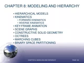
Chapter 8: Modeling and Hierarchy • Hierarchical Models • Kinematics • Forward Kinematics • Inverse Kinematics • Key-frame Animation • Scene Graphs • Constructive Solid Geometry • Octrees • Marching Cubes • Binary Space Partitioning Chapter 8: Modeling and Hierarchy
Hierarchical Models When the components of an animated object have extensive interrelationships, it is frequently useful to use a tree structure to model the object hierarchically. Torso Lower Head Right Thigh Left Thigh Right Arm Left Arm Upper Head Right Ankle Left Ankle Thus, for example, the left foot swivels on its own axis, but also rotates with the left ankle as the knee bends. Both the foot and the ankle are affected by the spinning of the thigh on the hip, and all of the leg components accompany the torso as it rises, falls, and turns. Right Hand Left Hand Right Eyeball Left Eyeball Right Foot Left Foot Right Iris Left Iris Chapter 8: Modeling and Hierarchy
Kinematics Forward Kinematics HIPS LEFT UPPER LEG RIGHT UPPER LEG LEFT LOWER LEG RIGHT LOWER LEG LEFT FOOT RIGHT FOOT When modeling a hierarchical animated object, a common method is forward kinematics, which uses a simple top-down approach. To turn the torso, note that it’s connected to the upper legs, which are connected to the lower legs. If the torso rotation is strictly applied to the hierarchy, the feet seem to slide over the floor. If the torso rotation is not strictly applied to the hierarchy, the feet are (painfully) left behind. Chapter 8: Modeling and Hierarchy
Kinematics Forward Kinematics A child object inherits the transforms of its parent, and the parent inherits the transforms of its ancestors all the way up the hierarchy to the root object, compelling the use of a top-down approach when positioning and animating the hierarchies. To reposition the mannequin’s right foot to rest atop the soccer ball... First, rotate the right thigh so the entire leg is above the ball... Next, rotate the right shin so the foot is near the top of the ball... And finally, rotate the right foot so it is parallel to the top of the ball. While forward kinematics affords considerable control over the exact placement of every object in the hierarchy, the process can become tedious with large and complex hierarchies. Chapter 8: Modeling and Hierarchy
Kinematics Inverse Kinematics With inverse kinematics, the graphics programmer specifies the effect that is desired and the animation automatically moves towards that goal. Avoiding the “canned” motion of forward kinematics, IK opens the animation up to multiple degrees of freedom. At each joint, constraints are specified in order to prevent awkward movements that defy the physical limitations of the object being modeled. Chapter 8: Modeling and Hierarchy
Kinematics Inverse Kinematics Inverse kinematics attempts to interpolate between current and goal positions and orientations, obeying whatever physical constraints have been provided to ensure that desired connectivity and natural appearance be maintained. The primary problem with inverse kinematics is the fact that there may be several solutions to the problem, making it necessary to set up an elaborate system of constraints and rest positions to ensure proper movement. Chapter 8: Modeling and Hierarchy
Kinematics Controlling Kinematics In Forward Kinematics, the modeler starts at the top of the hierarchy, rotating and moving joints until the entire joint chain is correctly posed. In Inverse Kinematics, the modeler manipulates a handle deep within the hierarchy and the higher-level joints adjust (within their constraints) to the manipulation. Chapter 8: Modeling and Hierarchy
Kinematics Case Study: Two-Link Arm L2 y 2 L1 4 1 3 x In Chapter 8: Modeling and Hierarchy
Key-frame Animation Key-frame animation is used to automate the interpolation of graphical object motion between successive snapshots specified by the modeler. The “in-between” frames are calculated, with the position of the scene objects computed according to a specified trajectory. In addition to position, other graphical features (size, shape, color, etc.) can be interpolated via key-frame animation. Chapter 8: Modeling and Hierarchy
Scene Graphs A scene graph is a hierarchical ordering of the components of a graphical scene so that parent nodes affect child nodes. By organizing the graphical components in this manner, modeling the behavior of secondary components is less complicated, since certain aspects of that behavior are essentially inherited from the corresponding primary components. Chapter 8: Modeling and Hierarchy
Constructive Solid Geometry Constructive solid geometry provides a method for modeling 3D objects by combining primitive geometric shapes (spheres, cubes, etc.) into compound 3D objects by means of basic boolean operations. Boolean Union Boolean Difference Boolean Intersection The hierarchical nature and simplicity of the CSG approach has made it particularly popular in CAD/CAM systems. Chapter 8: Modeling and Hierarchy
Octrees 3D objects may be modeled by means of octrees, which iteratively subdivide space into cubical subregions (called voxels) until each is either completely empty or filled with a particular type of object. In addition to providing a convenient mechanism for storing 3D data, this approach provides a simple means for resolving hidden surfaces and controlling level of detail. Chapter 8: Modeling and Hierarchy
Marching Cubes 2D Example The voxel approach to volume rendering can be altered somewhat to achieve a better approximation of the original object (albeit at a much higher cost with respect to processing time) via marching cubes. A grid of points is set up, with some of the grid points inside the object being rendered (in this case, a circle), and the rest outside. The midpoint of each border segment (i.e., a grid segment with one endpoint inside the object and the other outside) is determined. These points are joined to form an approximation of the circular object. Chapter 8: Modeling and Hierarchy
Marching Cubes Extending to 3D This approach can be extended to three dimensions by first noticing that there are 15 basic ways in which a 3-D object’s interior and exterior can relate to a cube that it intersects. The red vertices denote corners that have tested as inside the object and the blue vertices denote corners that have tested as outside the object. Chapter 8: Modeling and Hierarchy
Marching Cubes Midpoint-Based Intersections By only rendering the midpoint-based planar intersections with the individual voxels, we can obtain a good approximation of the original object, and can resolve the hidden surface problem relatively easily. Of course, the finer the grid, the better the resulting image. Chapter 8: Modeling and Hierarchy
Marching Cubes Actual Intersections The image can be dramatically improved by using the actual intersection points between the object and the grid segments instead of the midpoints. Naturally, this “adaptive” approach significantly increases the computational complexity of the algorithm. Chapter 8: Modeling and Hierarchy
Hidden Surface Removal Binary Space Partitioning B C B front back A D1 A,D2,E,F C,D1 F D2 E Using a binary tree structure, we can partition the object space into numerous half-spaces, and use the viewpoint’s position in these half-spaces to determine the order in which they should be rendered. Pick a polygon and split the space into the part in front of the polygon and the part in back of it (splitting all intersected polygons) Chapter 8: Modeling and Hierarchy
Hidden Surface Removal Binary Space Partitioning B C front back B A D1 F C D2 F E front front back D2 A D1 back E B C C B front back B B A D1 A D1 F C,D1 front back F D2 F D2 E E front back F C D2,E A front front back D2,E A D1 Continue this process The process ends when each tree node contains one object (or sub-object) Chapter 8: Modeling and Hierarchy
Hidden Surface Removal Binary Space Partitioning B front back F C front front back D2 A D1 back E C C B B A A D1 D1 F F D2 D2 E E Viewpoint Viewpoint When determining the order in which the objects should be displayed (e.g., in a painter’s algorithm) for a particular viewpoint, merely traverse the BSP tree recursively: If the viewpoint is in front of the root, traverse Back-Root-Front; otherwise, traverse Front-Root-Back. Example 1 Example 2 B-subtree: in front C-subtree, B, F-subtree C-subtree: in front C, D1 F-subtree: in front A, F, D2-subtree D2-subtree: in back D2, E Complete Traversal: C, D1, B, A, F, D2, E B-subtree: in back F-subtree, B, C-subtree F-subtree: in front A, F, D2-subtree D2-subtree: in front E, D2 C-subtree: in front C, D1 Complete Traversal: A, F, E, D2, B, C, D1 Chapter 8: Modeling and Hierarchy