Interfacing DAC/ADC without Peripheral Controller
Interfacing DAC/ADC without Peripheral Controller. Dr A Sahu Dept of Computer Science & Engineering IIT Guwahati. Outline. Peripheral communications DAC Properties Generic Model Interfacing ADC Properties Generic Model Interfacing Display. Introduction. R A M. Processor.


Interfacing DAC/ADC without Peripheral Controller
E N D
Presentation Transcript
Interfacing DAC/ADC without Peripheral Controller Dr A Sahu Dept of Computer Science & Engineering IIT Guwahati
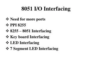
Outline • Peripheral communications • DAC • Properties • Generic Model • Interfacing • ADC • Properties • Generic Model • Interfacing • Display
Introduction R A M Processor • Peripherals : HD monitor, 5.1 speaker • Interfaces : Intermediate Hardware • Nvidia GPU card, Creative Sound Blaster card • Interfaces : Intermediate Software/Program • Nvidia GPU driver , Sound Blaster Driver software
Primary function of MPU • Read Instruction from memory • Execute instruction • Read/Write data to memory • Some time send result to output device • LEDs, Monitor, Printer • Interfacing a peripheral • Why: To enable MPU to communicate with I/O • Designing logic circuit H/W for a I/O • Writing instruction (S/W)
Transmission controller • Transmission Controller: • MPU control, Device Control (DMA) • Type of IO mapping • Peripheral (IN/Out), Memory mapped IO (LD/ST,MV) • Format of communication • Synchronous (T & R sync with clock), Asynchronous • Mode of Data Transfer • Parallel, Serial (UART) • Condition for data transfer • Uncond., Polling, Interrupt, Ready signal, Handshake
Digital to Analog Converter • Used for play sound in speaker • Used by AC97 (Audio codec) • MP3 Sound store digital format in HDD • Slow as compared to processor/MPU • Parameters • Resolution (8 bit/16 bit) • Settling time (1micro sec)
D/A converter FS 7 • FullScaleOutput=(FullScaleValue – 1LSBValue) • 1MSB Value=1/2 * FSV 6 Digital to Analog Converter D2 LSB 5 Vo 4 Analog output D1 Analog Output 3 2 D0 1 0 000 001 010 011 100 101 110 111 Digital Inputs
Circuit Realization 2.5K 4K D3=8 5K D2=4 Vout 10K D1=2 20K D0=1 • Vo= Vref/R * ( A1/2+ A2/4+…An/2n) • Vo is proportional to values of Data Bits Value
Resistive Ladder Network Require two type Resistor But small value 5K and 10K Practical DAC : R-2R ladder network R R E G I S T E R 2R Vout + R 2R R Resistor 2R R R+R=2R 2R 2R||2R=R
Glitches cause waveform distortion, spurs and elevated noise floors High-speed DAC output is often followed by a de-glitchingSHA (Hold Buffer) Output Glitches • Cause: Signal and clock skew in circuits • Especially severe at MSB transition where all bits are switching – • 0111…111 → • 1000…000
Performance of DAC • Resolution • Reference Voltages • Settling Time • Linearity • Speed • Errors
Resolution • Amount of variance in output voltage for every change of the LSB in the digital input. • How closely can we approximate the desired output signal(Higher Res. = finer detail=smaller Voltage divisions) • A common DAC has a 8 - 12 bit Resolution N = Number of bits
Vout Vout Desired Analog signal Desired Analog signal 111 110 110 1 8 Volt. Levels 2 Volt. Levels 101 101 100 100 011 011 010 010 001 001 0 0 000 000 Digital Input Digital Input Approximate output Approximate output Resolution Poor Resolution(1 bit) Better Resolution(3 bit)
Reference Voltage • A specified voltage used to determine how each digital input will be assigned to each voltage division. • Types: • Non-multiplier: internal, fixed, and defined by manufacturer • Multiplier: external, variable, user specified
Settling Time • Settling Time: The time required for the input signal voltage to settle to the expected output voltage(within +/- VLSB). • Any change in the input state will not be reflected in the output state immediately. There is a time lag, between the two events.
Analog Output Voltage +VLSB Expected Voltage -VLSB Time Settling time Settling Time
Linearity(Ideal Case) NON-Linearity(Real World) Desired Output Desired/Approximate Output Approximate output Analog Output Voltage Analog Output Voltage Digital Input Digital Input Miss-alignment Perfect Agreement Linearity
High Gain Desired/Ideal Output Analog Output Voltage Low Gain Digital Input Errors Gain • Gain Error: Difference in slope of the ideal curve and the actual DAC output High Gain Error: Actual slope greater than ideal Low Gain Error: Actual slope less than ideal
Speed • Rate of conversion of a single digital input to its analog equivalent • Conversion Rate • Depends on clock speed of input signal • Depends on settling time of converter
Generic Used: Audio player • Used when a continuous analog signal is required. • Signal from DAC can be smoothed by a Low pass filter Piece-wise Continuous Output Analog Continuous Output Digital Input n bit DAC 0 bit 011010010101010100101 101010101011111100101 000010101010111110011 010101010101010101010 111010101011110011000 100101010101010001111 Filter nth bit
Interfacing 8-bitDAC with 8085 • Design an output port with Address FFH to interface 1408 DAC • Write a program to generate a continuous RAMP waveform Output Time
Interfacing Diagram Address Bus (16bit) D7 D6 D5 D4 D3 D2 D1 D0 74LS373 Latches 1408 LE 8085 MPU A15 A0 Data Bus (8bit) A7 A6 A5 A4 A3 A2 A1 A0 D7 D0
Program to generate continuous RAMP waveform MVI A, 00H ; Load Acc with first I/P DTOA: OUT FFH ; Output to DAC MVI B, COUNT ; Setup Reg. for Delay DCR B JNZ DELAY INR A ; Next Input JMP DTOA ; Go back to Output Slope of RAMP can be varied by changing Delay
Analog to Digital Conversion 111 • ADC are slower then DAC • Interfaced using Status Check 110 Analog to Analog Converter LSB 101 Vi D2 100 Digital output D1 Analog Input 011 010 D0 001 000 0 1 2 3 4 5 6 7 Analog Input
Sampling Fourier Transform Sampling Concepts
The process of reconstructing a signal from its values at discrete instants of time Zero order hold or One Point Linear or Two Point Band limited or Low pass Filtering Interpolation
Algorithm for finding unknown N • Suppose my range is 0-1024 and assume some value of N between 0-1024 • You have to find the value of N • You can ask me (what about value X) • Answer ( N>X, N<X, N==X) • Operation with X (X++; X*2, X^2, X/2, X--)
Algorithm for finding unknown N • What is the best Algorithm to find • Sequential ( increase X till X==N) O(N) algorithm • Successive approximation: (Binary Search) • Say R/2 as CMP( R/2, N) === if equal stop IF (R/2 < N) CMP (R/2+R/4,N) ELSE CMP (R/2-R/4, N) • If you have N persons to do the comparisons • Ask to all people and Gather the information • Mix of Both approach • If you have M comparator
A/D Conversion Techniques • Counter or Tracking ADC • Successive Approximation ADC • Most Commonly Used • Parallel or Flash ADC • Fast Conversion
Block diagram Waveform Operation Reset and Start Counter DAC convert Digital output of Counter to Analog signal Compare Analog input and Output of DAC Vi < VDAC Continue counting Vi = VDAC Stop counting Digital Output = Output of Counter Disadvantage Conversion time is varied 2n Clock Period for Full Scale input Counter Type ADC Control Logic Clock Counter DAC Vi
Most Commonly used in medium to high speed Converters Based on approximating the input signal with binary code and then successively revising this approximation until best approximation is achieved SAR(Successive Approximation Register) holds the current binary value Block Diagram Successive Approximation ADC
Circuit waveform Logic Flow Conversion Time n clock for n-bit ADC Fixed conversion time Serial Output is easily generated Bit decision are made in serial order Successive Approximation ADC
Very High speed conversion Up to 100MHz for 8 bit resolution Video, Radar, Digital Oscilloscope Single Step Conversion 2n –1 comparator Precision Resistive Network Encoder Resolution is limited Large number of comparator in IC Parallel or Flash ADC
Generic ADC Vinput A/D Converter Digital O/P START RD Ready Start
Interface ADC using Status Check Address Bus (16bit) Vinput Tri-State Buffer A/D Converter Digital O/P 8085 MPU A15 A0 A6 A5 A4 A3 A7 82H Data Bus (8bit) 74 LS 138 E1 E3 E2 RD START o2 D7 D0 o1 81H Ready 80H o0 Start IO/R IO/W
Program to Interface ADC OUT 82H ; Start Conversion TEST: IN 80H ;Read DR Status RAR ; Rotate Do to carry JC TEST ; if Do==1 conv. done IN 81H ; Read the output RET ; Return
Display 7 Seg 9 Seg 16 Seg 3x5 DotMatix 5x7 9x11 Dot Matrix Display Panel 25x80 character monitor
Generic Model of Display Decoder Or Memory Display Monitor/LEDs Data ASCII/BCD Time to Decode Time to Display
a b f 1 1 0 a 0 D 1 5 0 1 b 5 1 g C 1 1 c f 0 Common Cathode 0 B 5v e 1 5v 1 1 1 A g 1 1 d 1 c 0 LT e 5V 5V RBI 1 1 d RBO BI Decoder 7 Segment LED Interfaces • Data to 7 Seg Decoder
Blank Blank 0 0 1 a b c d e f g a b c d e f g a b c d e f g a b c d e f g 5V a b c d e f g 1 1 RBI RBO RBI RBO RBI RBO RBI RBO RBI RBO D C B A D C B A D C B A D C B A D C B A 0 0 0 0 0 0 0 0 0 0 1 1 0 0 0 0 0 1 1 1 Multiple 7 Segment LED Interfaces • Data to 7 Seg Decoder
Reference • R S Gaonkar, “Microprocessor Architecture”, Unit II preface, Chapter 13