Download
1 / 26
260 likes | 410 Views
CNGS Primary and Target Instrumentation. OUTLINE Beam Position System update on acquisition system Beam Profile System the principle of OTR measurements Beam Loss System Beam Current Transformers Target Beam Position Monitor results of testing a monitor in air

E N D
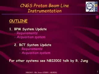
CNGS Primary and Target Instrumentation OUTLINE • Beam Position System • update on acquisition system • Beam Profile System • the principle of OTR measurements • Beam Loss System • Beam Current Transformers • Target Beam Position Monitor • results of testing a monitor in air • construction & integration of CNGS target monitor
Original 18 Button Electrode BPMs in TT41 60mm Aperture 4 Stripline Couplers in TT40 will see both LHC & CNGS beams Modified 1. CNGS Beam Position Monitoring CNGS Beam Position Measurement Requirements Intensity Range: 11012 to 3.51013
1. CNGS Beam Position Monitoring CNGS Beam Position Measurement Acquisition System • Each signal is compressed by a logarithmic amplifier, filtered and applied to a differential amplifier. • The position response is: Pos [log(A/B)] = [log(A)-log(B)] (Vout) where Vout is the voltage difference between the log-amp outputs
1. CNGS Beam Position Monitoring CNGS Beam Position Measurement Front-end
1. CNGS Beam Position Monitoring CNGS Beam Position Measurement Front-end Status: • Design completed • Manufacture underway - final boards ready by end 2005 • EPLD coding complete - control of timing - calibration - manchester encoding • Linearity and Resolution - test bench available - tests performed once digital acquisition platform is available (Autumn 2005) Autotrigger Calibrator Out Right Left Up Down Control EPLD ADC Log Amps Integrators
Based on LHC BPM system: VME64x Digital Acquisition Board - DAB64x (TRIUMF, Canada) Altera Stratix (EP1S20) FPGA - use same code as for LHC BPMs Manufacture underway - boards ready by end July 2005 Mezzanine Card under test - receives info from 6 front-ends - performs manchester decoding - Xilinx FPGA treats data to give correct input for DAB64x Final configuration - 2 DAB64x with 2 mezzanines - processing data from 23 CNGS PUs 1. CNGS Beam Position Monitoring CNGS Beam Position Measurement Acquisition System
1. CNGS Beam Position Monitoring CNGS Beam Position Measurement Acquisition System Why this choice of front-end? low cost – as it requires only 1 coax cable per pick-up. large dynamic range without requiring gain switching. simple engineering auto-triggered - no requirement for external timing in the tunnel Why this choice of digital acquisition? uses standard LHC BPM digital acquisition card - final board ready by mid 2005 - software architecture already in place - guarantees hardware & software support minimal development for CNGS team - develop a single (relatively simple) mezzanine board to convert CNGS signal to compatible format
Layout TT40: LHC and CNGS beams 3 monitors TT41: CNGS beams only 8 monitors last one just in front of exit window 2. CNGS Beam Profile Monitoring CNGS Beam Profile Measurement Requirements Requested precision for all monitors 5 to 10% Dynamic range for intensity: Factor 20 for CNGS Factor 8’000 for CNGS & LHC (TT40) Smallest beam size to be measured at target 1s between 0.3 & 0.8mm
2. CNGS Beam Profile Monitoring Choice of CNGS Beam Profile Measurement System Traditionally SEM grids Choice for CNGS Optical Transition Radiation (OTR) screens CCD acquisition Many current & future CERN systems using this approach Advantages: Twodimensional information High resolution: ~ 400 x 300 = 120’000 pixels More economical Time resolution depends on choice of image capture device - CCD in video mode limited to 50Hz - CCD in fast frame mode can operate in the kHz range - Photomultiplier in the MHz range - Streak camera in the GHz range
2. CNGS Beam Profile Monitoring OTR – The Principle Radiation emitted when a charged particle beam goes through the interface of 2 media with different dielectric constants (surface phenomenon) OTR Screen Beam Intensifier - CCD Mirror Capturing emitted radiation on a CCD gives 2D beam distribution
2. CNGS Beam Profile Monitoring OTR – The Principle (courtesy of R. Jung – DIPAC 2003) Capturing emitted radiation on a CCD gives 2D beam distribution
2. CNGS Beam Profile Monitoring OTR – Screen Choice (courtesy of R. Jung – DIPAC 2003) Capturing emitted radiation on a CCD gives 2D beam distribution
2. CNGS Beam Profile Monitoring CNGS BTVG System For setting-up & low intensity beams Ti screens 12mm thickness For high intensity beams Carbon screens ~80mm thickness For TT40 dealing with both CNGS & LHC beams Al2O3 screens for setting-up with low intensity LHC beams Ti screensfor nominal operation
2. CNGS Beam Profile Monitoring Beam Profile Monitor Acquisition Cameras Standard CCD cameras for low radiation environments Rad hard solid state cameras for high radiation environments (last 2 or 3 monitors) TT40 images Acquisition Analogue transmission from camera to surface Cable lengths of up to 1km Analogue signal directly visible on TV screen Frame grabber digitises and stores picture Software determines beam sizes and calculates emittance Resolution Defined by field of view 34mm field of view gives 85mm per pixel CNGS extraction tests (2004)
3. CNGS Beam Loss Monitoring CNGS Beam Loss Detection Beam losses will be detected using: 18 standard 1 litre, SPS, nitrogen filled ionisation chambers 30 parallel plates with 5mm separation - ionisation length of 19cm efficiency of 1250 pairs per primary charge
3. CNGS Beam Loss Monitoring CNGS Beam Loss Acquisition Acquisition system based on reliable SPS system 1 card processes 8 beam loss channels integration over 20ms 2 individual gains per channel (0 & 40dB) 1 common gain (5 steps of 6dB) 12 bit ADCs (11 bits data + 1 polarity bit) 2 acquisitions per extraction - 1 before & 1 during for noise and offset subtraction Sensitivity/Resolution Max sensitivity for 800m cable ~6103 primary particles per bit - defined by capacitance used (Cmin 500pF in this case) Normal SPS transfer line operation with 1mF capacitor - gives a sensitivity of ~1107 primary charges per bit
First BCT sees both LHC & CNGS beams • Has to fulfill additional requirement of LHC bunch by bunch capability (i.e. 25ns resolution) 4. CNGS Beam Current Transformers CNGS Beam Current Monitoring Requirements Two Monitors – one at the beginning & one at the end of the line Absolute Accuracy of 1% for the Intensity Range: 11012 to 3.51013 New development for LHC - Fast BCT (BFCT) • 500MHz Bandwidth • Not required for CNGS • Low droop (~0.1%/ms) • 1% effect for CNGS
4. CNGS Beam Current Monitoring CNGS Beam Current Measurement Calibration Fast BCT fitted with calibration winding. Switched current source injects 128mA for 5ms • equivalent to 21010 charges in 25ns • same signal level as a CNGS train of 8.41012 protons Comparison between DCCT and single shot BFCT in the SPS Shaded region represent 2%
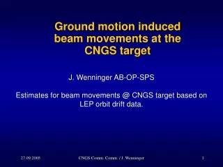
5. CNGS Target Beam Position Monitor Target position monitor fixed to target table & aligned wrt target 2nd BPM at 10m Last two BPMs used to provide position and angle
5. CNGS Target Beam Position Monitor CNGS Target Beam Position Measurement Requirements Final standard BPM of the proton beam line & target BPM used to provide position at the target setting up performed using final beam line BPM aiming at target rods verified & tracked using target BPM accuracy of measurement ±0.2mm in ±2mm central region. accuracy of measurement ±0.5mm outside ±2mm central region.
5. CNGS Target Beam Position Monitor Test Results from Stripline Coupler Pick-up in Air • Results presented at NBI2003 identified stripline coupler over button pick-up as most favourable candidate for CNGS target monitor
5. CNGS Target Beam Position Monitor Test Results from Stripline Coupler Pick-up in Air • Several further studies made to try and reduce wideband noise seen on the signals • Test of high voltage clearing electrodes • No effect seen for voltages up to 1500V • Tests of solenoid windings • No effect seen for 20A in 100 windings (~ 7mT) Final test made with old SPS • coupler installed in front of the • TT40 dump • CNGS BPM electronics unavailable • signals from a coupler under • vacuum compared with that in air • using oscilloscopes
5. CNGS Target Beam Position Monitor Test Results from Stripline Coupler Pick-ups in TT40 Log Amps will work with signal filtered at 200MHz • No discernible difference between signal at 200MHz from coupler in air or under vacuum • Signal levels different due to cable path and coupler stripline length
5. CNGS Target Beam Position Monitor Construction of the CNGS Target Station Monitor (BPKG) • Coupler Body • Aluminium alloy • lowers remnant radiation • Outer Surface Treatment • penetrating oxide layer • withstands radiation effects • gives thermal stability • Inner Surface Treatment • 30mm gold layer • withstands radiation effects • maintains good conductivity • Feedtroughs • Ceramic dielectric (vac seal) • simple 50W construction
5. CNGS Target Beam Position Monitor Integration of the CNGS Target Station Monitor (BPKG) • Signal Cabling • hermetically sealed SiO2 cables • very high radiation resistance • semi-rigid allows easier routing • 4 cables for signal output • 4 cables for calibration input
CNGS Primary and Target Instrumentation Summary All Beam Instrumentation now well defined Many systems already tested during TT40 extraction Remaining Issues: • Choice of camera for last 3 profile monitors (radiation levels) • Suitable candidates exist • Sensors tested for radiation hardness • Fully equipped cameras yet to be tested • Linearity of BPM system • Similar front-end gives good results in PS to SPS line • Test bench available once electronics ready • Performance of target pick-up in air • Will only be possible to evaluate with beam!