Download
1 / 62
640 likes | 691 Views
Delve into the board-level testing challenges, fault modeling, and test generation for interconnect faults with the IEEE1149.x Boundary Scan Standard. Explore application scenarios and techniques for effective implementation in this comprehensive guide.

E N D
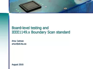
Board-level testing and IEEE1149.x Boundary Scan standard Artur Jutman artur@ati.ttu.ee August 2010
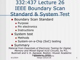
IEEE 1149.1 Boundary Scan Standard • Board level testing challenges • Fault modeling at board level (digital) • Test generation for interconnect faults • IEEE 1149.1 Boundary Scan Standard • Application of Boundary Scan
The Challenge of Board Testing Tested chips placed on board Only interconnects to be tested! Source: Intel Source: Elcoteq
static behavior dynamic behavior Modeling of Interconnect Faults • Net-level defect types and models • Short faults • Open faults • Delay faults • Noise/crosstalk • Ground bounce • …
Short Faults • Possible shorts: bond wire, leg, solder, interconnect • Shorts are usually modeled as wired-AND, wired-OR faults
Open Faults • Misplaced bond wire Misplaced component • Possible opens: bond wire, leg, solder, interconnect • Opens usually behave like stuck-at or delay faults
Tri-state connections • Main difference between logic circuits and board-level systems is the way the components are connected. • Typical board-level interconnect uses tri-state logic: logic-0, logic-1, and “high impedance” (switched off) state. Common notation: 0,1,Z. • There are special “enable” signals that control this additional state of the I/O pins.
Tri-state connections • Nets with several drivers • Nets with bi-directional pins
Tri-state net structure enable pin pin data data_in enable pin data data_in
Driver faults stuck-driving fault stuck-not-driving fault stuck-at fault Net opens stuck-at fault delay fault Net shorts zero dominance wired AND (mutual 0-dom.) one dominance wired OR (mutual 1-dom.) net dominance strong driver fault Specific faults in tri-state nets
IEEE 1149.1 Boundary Scan Standard • Board level testing challenges • Fault modeling at board level (digital) • Test generation for interconnect faults • IEEE 1149.1 Boundary Scan Standard • Application of Boundary Scan
? 1 0 1 1 • How many vectors are enough to cover all possible interconnect faults including delays and other dynamic effects? Short 0 0 Assume wired AND 1 0 Test Generation Algorithms Open Assume stuck-at-0 Opens usually behave like stuck-at or delay faults Shorts are usually modeled as wired-AND or wired-OR
? • What about • opens? Short Assume wired AND The Counting Sequence Open 00 00 Assume stuck-at-0 01 01 10 10 11 10 • Kautz [1] showed in 1974 that a sufficient condition to detect any pair of short circuited nets was that the serial codes must be unique for all nets. Therefore the test length is log2(N)
? • Some of the observed error responses are allowed codes. • How to improve the diagnosis? Short Assume wired AND The Modified Counting Sequence Open 001 000 Assume stuck-at-0 010 010 011 000 100 000 • All 0-s and all 1-s are forbidden codes because of open faults. Therefore the final test length is log2(N+2) • This method was proposed in 1982 by Goel & McMahon [2]
! • All-0 and all-1 codes are not forbidden anymore! Short Assume wired AND The True/Complement Code Open 00 11 00 00 Assume stuck-at-0 01 10 01 10 10 01 10 00 11 00 10 00 • To improve the diagnostic resolution Wagner proposed the True/Complement Code in 1987 [3]. • The test length became equal 2log2(N)
? • What about delay faults and other dynamic effects? Short Assume wired AND The True/Complement Code Open 00 11 00 00 Assume stuck-at-0 01 10 01 10 10 01 10 00 11 00 10 00 • Important properties of the True/Complement Code are: • there are equal numbers of 0-s and 1-s upon each line • Hamming distance between any two code words is at least 2
More complex case enable data data_in Open enable Driver Fault Short data data_in data data_in
Industrial approach to board test • Visual inspection • Optical/x-ray inspection • Smoke test ;-) • Power distribution test • Structural test • in-circuit test (ICT) • Boundary Scan (BS) • Test Processors/Cores (BIST) • Functional test (FT)
DIP PGA BGA Limitations of the Nail Probing Packaging styles Multilayer boards chip PCB conductive layers
Boundary Scan AOI and AXI Functional Testing Flying Probe In-Circuit Testing 1980 1990 2000 2010 Test Access Methods: Usage Trends Test access by different test methods
IEEE 1149.1 Boundary Scan Standard • Board level testing challenges • Fault modeling at board level (digital) • IEEE 1149.1 Boundary Scan Standard • Test generation for interconnect faults • Application of Boundary Scan
IEEE 1149.1 Boundary Scan: History • Early 1980’s – problem of test access to PCBs via “bed-of-nails” fixture • Mid 1980’s – Joint European Test Action Group (JETAG) • 1986 – US companies involved: JETAG -> JTAG • 1990 – JTAG Test Port became a standard [4]: • IEEE Std. 1149.1: Test Access Port and Boundary Scan Architecture comprising serial data channel with a 4/5-pin interface and protocol
Test Access Via Boundary Scan TDI TDO
Driver Sensor Virtual nails Test Access Via Boundary Scan • Defects covered: • driver scan cell, driver amp, bond wire, leg, solder, interconnect, solder, leg, bond wire, driver amp, sensor scan cell
Test Access Via Boundary Scan I/O Ethernet Controller TDI TDO TAP port CPLD FPGA TDI ADDR TMS TCK SRAM TCK DATA TMS TDO TMS TCK CONTROL TDI TDO mP A D C ADDR DDRAM Flash Non-BS IC DATA CTRL I/O Printed Circuit Board
Pin Pin BScan Cell CoreLogic CoreLogic TDI TDO TAPcontroller TCK ... some extra logic is needed for Test Access TMS BScan Device Non-BScan Device Boundary Scan basics For describing Boundary Scan devices BSDL (Boundary Scan Description Language) models are used
IEEE 1149.1 Device Architecture BS Cells Core Logic TDO TDI (TestDataIn) MUX MUX Bypass (TestDataOut) Identification Register Instruction Register (Test Mode Select) TMS TAP Controller TCK (Test Clock) Test Reset (Optional)
Scan Out (SO) Mode Data In (PI) Data Out (PO) 0 1 Capture Scan Cell Update Hold Cell 0 1 D Q D Q Clk Clk UpdateDR Scan In (SI) ShiftDR ClockDR Typical Boundary Scan Cell (BC_1) • BC_1 is used both at input and output pins
Instruction SAMPLE /PRELOAD EXTEST BYPASS IDCODE INTEST CLAMP HIGHZ RUNBIST USERCODE Status Mandatory Mandatory Mandatory Optional Optional Optional Optional Optional Optional Boundary Scan Instructions
Core Logic Core Logic Mode Mode ShiftDR ShiftDR SO SO TDI TDO 0 1 0 1 0 1 0 1 D Q D Q D Q D Q Clk Clk Clk Clk ClockDR ClockDR UpdateDR UpdateDR SI SI Boundary Scan Working Modes • SAMPLE/PRELOAD instruction – sample mode • Get snapshot of normal chip output signals • Get snapshot of normal chip output signals
Core Logic Core Logic Mode Mode ShiftDR ShiftDR SO SO TDI TDO 0 1 0 1 0 1 0 1 D Q D Q D Q D Q Clk Clk Clk Clk ClockDR ClockDR UpdateDR UpdateDR SI SI Boundary Scan Working Modes • SAMPLE/PRELOAD instruction – preload mode • Shift out snapshot data and shift in new test data to be used later • Shift out snapshot data and shift in new test data to be used later
Core Logic Core Logic Mode Mode ShiftDR ShiftDR SO SO TDI TDO 0 1 0 1 0 1 0 1 D Q D Q D Q D Q Clk Clk Clk Clk ClockDR ClockDR UpdateDR UpdateDR SI SI Boundary Scan Working Modes • EXTEST instruction – driving and sensing: • Test off-chip circuits and board-level interconnections • Test off-chip circuits and board-level interconnections
Core Logic Core Logic Mode Mode ShiftDR ShiftDR SO SO TDI TDO 0 1 0 1 0 1 0 1 D Q D Q D Q D Q Clk Clk Clk Clk ClockDR ClockDR UpdateDR UpdateDR SI SI Boundary Scan Working Modes • EXTEST instruction – shifting • Shift out snapshot data and shift in new test data to be used later • Shift out snapshot data and shift in new test data to be used later
TDI D Q To TDO Shift DR Clk Clock DR Core Logic Core Logic Core Logic TDI TDO BYPASS BYPASS SAMPLE Boundary Scan Working Modes • BYPASSinstruction: • Bypasses the corresponding chip using 1-bit register Similar instructions: CLAMP, HIGHZ
TDO TDI Version Part Number Manufacturer ID 1 4-bits Any format 11-bits Coded form of JEDEC 16-bits Any format Boundary Scan Working Modes • IDCODE instruction: • Connects the component device identification register serially between TDI and TDO in the Shift-DR TAP controller state • Allows board-level test controller or external tester to read out component ID • Requiredwhenever a JEDEC identification register is included in the design
DR Branch IR Branch TAP Controller State Diagram The TAP state diagram has two main branches and two idle states. Shift IR and Shift DR states are used to insert instructions and test data into the BS device. These are the most important states. The number of states is exactly 16 (to avoid some undefined states) TMS signal is used to move through the states
Boundary Scan in Motion (Demo) • http://www.testonica.com
IEEE 1149.1 Boundary Scan Standard • Board level testing challenges • Fault modeling at board level (digital) • IEEE 1149.1 Boundary Scan Standard • Test generation for interconnect faults • Application of Boundary Scan
BSC implementation • One or more BSC at each system input or output of on-chip system logic (core logic) • BSC may be connected to chip-internal signals • No BSC on: • TAP pins (TCK, TMS, TDI, TDO, TRST) • Compliance Enable Pins • Non-digital pins (e.g. analog pins, power pins) • No logic between BSC and I/O pin it is connected to (a buffer is allowed)
VCC Analog BScan Cell CoreLogic (digital) + – GND TDO TDI TAPcontroller TCK TMS BSC implementation
on-chip system logic 24 Pin BSC implementation • Input:
on-chip system logic 7 Pin BSC implementation • 2-state output:
“control” 6 on-chip system logic “data” 5 Pin Driver BSC implementation • 3-state output:
“control” 6 on-chip system logic “data” 5 Pin Driver BSC implementation • Bi-directional, 2-cell:
“control” 2 “out” 1 on-chip system logic Pin Driver “in” 0 BSC implementation • Bi-directional, 3-cell:
“control” 4 “data” on-chip system logic 3 Pin Driver 2 Pin Driver BSC implementation • 3-state outputs, shared control cell:
TAP TAP TAP Interconnect Logic Interconnect Logic Board-level Test using Boundary Scan (in theory) • Infrastructure test (generated by using BSDL models) • Interconnect test (BSDL models + interconnection netlist) JTAG connector Board (UUT) TDI TMS TCK TDO