Download
1 / 12
120 likes | 280 Views
Development of the CMS Silicon Strip Tracker Readout. Matthew Noy Imperial College London 7 th April 2004, IOP, Birmingham. Introduction. LHC: CERN, Geneva. To replace LEP (same tunnel) starts ~2007 14 TeV P-P collisions (+ HI programme) Design L ~ 10 34 cm -2 s -1

E N D
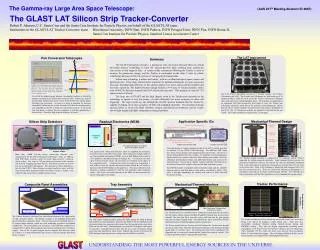
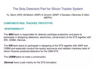
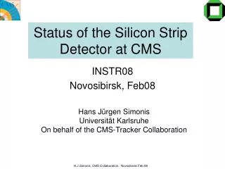
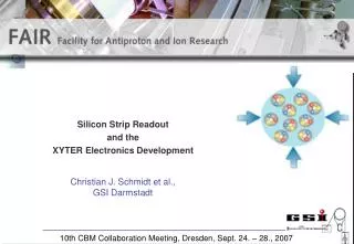
Development of the CMS Silicon Strip Tracker Readout Matthew Noy Imperial College London 7th April 2004, IOP, Birmingham
Introduction • LHC: CERN, Geneva. • To replace LEP (same tunnel) starts ~2007 • 14 TeV P-P collisions (+ HI programme) • Design L ~ 1034 cm-2s-1 • Bunch Crossing ~40MHz • CMS: • 1 of 2 General Purpose detectors • Solonoidal design, v. dense 12kTonnes • Largest superconducting magnet • L~21m, D~14m • Higgs, SUSY, others
Silicon Microstrip Tracker • Cylindrical volume of ~25m3 is instrumented • ~210m2 of Si • 107 Si Microstrip Channels • length 5.4m, Diameter 2.4m • Analogue readout • No L1A decision involvement • On detector analogue buffering • APV25 (IC/RAL col.) • Expected rate ~100kHz • ~80000 Analogue Optical readout links • Harsh environment • Operates in 4T magnetic field • Expected 10MRads integrated over lifetime • Everything on-detector is rad-hard
Generic 40MHz Occupancy ~ few % Total noise < 2000e- Control Token ring arch. Timing ~ 1ns (indv. ch.) I2C on detector control L1A ~ 100kHz Readout 40MSs-1 ~ 3GBs-1FED-1 Serialised: 256:1 Undersampling Zero Suppression etc. Control and Readout Architecture Off detector (non-rad.) On detector (rad.) 100m
96 Tracker Opto Fibres CERN Opto- Rx 9U VME64x Analogue/Digital JTAG 12 12 12 12 12 12 12 12 FPGA Configuration Compact Flash FE-FPGA Cluster Finder VME Interface VME-FPGA BE-FPGA Event Builder TCS TTC TTCrx DAQ Interface Buffers Power DC-DC Temp Monitor Front-End Modules x 8 Double-sided board TCS : Trigger Control System FED Architecture/Interfaces • 9U VME64x Form Factor • VME module / Configuration • Modularity matches Opto Links • 8 x Front-End “modules” • 96 channels in tot. • OptoRx/Digitisation/Cluster Finding • Back-Endmodule / Event Builder • Power module • Other Interfaces: • TTC : Clk / L1 / BX • DAQ : Fast Readout Link • TCS : Busy & Throttle • JTAG : Test & Configuration Xilinx Virtex-II FPGA
JTAG OptoRx VME64x 9U board CFlash 34 x FPGAs 96 channels Memories Analogue Power TTC FE Unit “Primary” Side First FED Prototype (01/03)
CMS Tracker FED Zoom in on FE Unit OpAmps Dual ADCs Rsense = 100 Ohm Delay FPGAs “OptoRx” Resistor Packs Test Connector TrimDAC “Primary” Side Front-End Unit = 12 channels “OptoRx” modules CERN project Commercial Package with PIN Diode + Custom Analogue ASIC
RAL responsibilities Design/Layout Complex analogue sec. Firmware Provide/test functionality Low level software Closely linked to firmware Abstraction to middle UI Brunel responsibilities software IC responsibilities Modelling Design sufficient? Performance Does it do what we need? Software Online interfaces Test benches Internal/Fed Tester FED Collaboration
Design Verification Hardware (Hw) Performance Permits firmware Has required interfaces Firmware (Fw) Performance Provides functionality Respects interfaces Stable Software (Sw) Robust Efficient Abstracts complexity to user interface Interfaces/respects online environment Nearly there… FED in use Pisa, CERN (now), Lyon (after Easter) Beam Test (25ns) June and Oct. 04. LHC-like conds. Development and Testing I
Timing control crucial Time-of-flight delays Fibre propagation differences Undersampling readout Careful choice of sampling point Xilinx Virtex II FPGA DCM Implementation of clock skewing 96 independent ADC clock points Timing Functionality (M. Noy) 32 fine steps of ~ 800 psec
Need ~500 Have seen failures Problem for similar ATLAS boards BGA Soldering problems (batch 10.03) Overcome with latest batch (03.04) Produced in industry JTAG B.S. amongst others. Internal/Self Testing (M. Noy) Significant software task Development of robust algorithms Abstract complexity Simple interface Pass/Fail decision Provides Rapid, accurate feedback to assembly co. Identification of: Assembly mistakes Component failures Development and Testing II
FED card First off detector electronics 9U VME form 96 ADC ch, ~3GBs-1 V. dense analogue sec. 36 FPGAs (big, complex) Hw, Fw, Sw High degree of development,testing required, and done Robust, stable, nearly full functionality Performant Production Begin 2005 We will be ready. In Use CERN, Pisa (now) Lyon (soon) Beam Test June, Oct. 04. Summary