Recent Experience with CMS Tracker OptoLinks: Integration and Calibration Insights
This presentation highlights the recent experiences and findings from the CMS Tracker's opto-links, detailing the integration, connection, and testing phases from the 2008 workshop to more current operations in 2009. It discusses digital and analogue control link performance, calibration procedures, and monitoring measurements. Challenges such as low gain detections and power supply issues are outlined. Insights into the ongoing work and preliminary results point towards optimizing CMS Tracker operations and ensuring efficient data transfer and communication systems.

Recent Experience with CMS Tracker OptoLinks: Integration and Calibration Insights
E N D
Presentation Transcript
CMS strip-Tracker Recent optolinks experience Karl Gill, Francesco Palmonari Thanks also to strip-TK commissioning team (and specifically Erik Butz, Steven Lowette, Stefano Mersi)
Outline • Very brief recap of system in CMS Tracker • 4/2008 o-links workshop describes integration, connection and test experience • http://indico.cern.ch/conferenceDisplay.py?confId=29674 • Cover here more recent (2009) Experience • Digital control links • Analogue readout links • Examples of recent calibration (‘monitoring’) measurements • More a flavour of ‘work in progress’ than concrete results • Conclusion/outlook
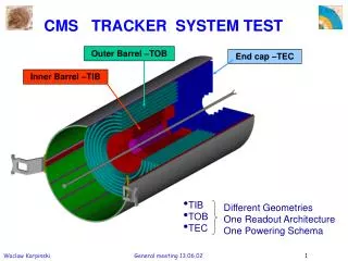
CMS TK link system(s) • Si-strips • Readout links • 36234 lit fibres • 40MSamples/s • 8 bit range • Control links • I2C configuration, trigger, clock, reset • 80Mbit/s • 2848 lit fibres
Timeline/activities Operations Cosmic + LHC TIB/TID only TIB/TID only (Re)commissioning for operation 4°C 10°C Debug + Retest Low gain DAQ analysis + Low gain Lengths X-check Connection + Test 2008 2009 2010
Timeline/activities/effort For info: Approx. FTE ~10 Operations Cosmic + LHC TIB/TID only TIB/TID only (Re)commissioning for operation 4°C 10°C Debug + Retest Low gain DAQ analysis + Low gain Lengths X-check ~2 Connection + Test ~0.1 2008 2009 2010
Digital links • Little to report for digital control/trigger/timing links in token rings • 5/356 rings failed to work properly in 2008 • 2 recovered changing TRx parts at FEC • 1 using redundant optohybrid at front-end • 2 unrecoverable so far • (power supply cabling problems suspected in patch panel within CMS magnet) • Take a look at next shutdown • Did not yet measure power margins • Would be useful thing to do to have a reference for future behaviour • To be discussed with other subdetectors with same links
Analogue readout • Data transfer: • 2 APV chip outputs multiplexed to 40Msamples/s • digital header/trailer plus 256 strips input to optolink
Readout links monitoring - 1 • Optolinksnot (yet) monitored directly at regular or fixed intervals • Instead, checks made when calibrations (re)done • Typically during long breaks in operation, or done after serious problems/change of temperature inside Tracker • Bias, gain, noise contribution measured. • (related to laser threshold and efficiency (but laser driver, MUX and readout chip performance also partly entangled in the results…) • Main parameters are T-dependent (and will be affected later by irradiation, wearout)
Analogue Link Characteristics OUTPUT • I2C Programmable on analogue optohybrid: • Bias-point (0-127) • 0.45 I2C counts/mA • Gain settings (0, 1, 2, 3) • (‘0’) 5, (‘1’) 7.5, • (‘2’) 10, (‘3’) 12.5 mA/V • Calibration procedure • Loop over gains 0 to 3, ramping Bias-point 0-50 for each laser. • Check output and select optimal bias point (+2 I2C counts above zero light) and gain setting (nearest 0.88). • Noise is rms of signal at given bias point • Store noise at analogue pedestal level INPUT
Readout links ‘monitoring’ - 2008 • After first commissioning of detector (7/2008) very good situation. • Almost all links functioning with good signal size. • 2-3 attempts to recover the ~1% low output (gain setting=3) channels • Cleaning only MPO connections at back-end • 10% of 340 connections significantly improved • 12/08: First comparison made of DAQ output and earlier OTDR tests • 3.7% of channels flagged with anomalous peaks/losses with OTDR • Small but clear correlation between OTDR comments and gain measured with DAQ (see next slide) • Additional targeted microscope inspection and OTDR measurements in 08/09 shutdown • Besides 11 known bad, additionally 40 bad connections identified inside detector plus 18 at PP1, not all fatal but unrecoverable for time being • Main issue was difficulty to have good access to system for intervention and rapid reiteration of opto-scan measurement • Low priority during operations as these are considered refinements on 1% of complex system with other bigger concerns (particularly cooling in 2008). • No DAQ feedback during 08/09 shutdown due to cooling plant refurbishment
First comparison OTDR and DAQ • OTDR comment classes (refers to size of reflection and losses observed): • MFS Small no loss – 98 instances • MFS Medium no loss – 30 instances • MFS Big no loss – 15 instances • MFS very Big no loss – 3 instances • MFS small loss – no instances • MFS medium loss – no instances 2 • MFS Big loss – no instances 2 • MFS Very Big loss – no instances2 • MU Small no loss – 9 instances • MU Medium no loss – 13 instances • MU Big no loss – 319 instances • MU Very Big no loss - 185 instances • MU Small with loss – 1 instances • MU Medium with loss – 3 instances • MU Big with loss – 168 instances • MU Very Big with loss – 549 instances 2) This kind of problem with MFS peak >18dB was object of a repairing campaign (connector cleaning) during fiber connection activity.
Readout links monitoring - 2009 • In 2009, during operation 7/09 onwards, full readout and control system always under close surveillance • Degradation/anomalies are reported/followed up • System was very stable from point of view of optical links • (see later slides) • Some S/N losses seen where wrong fibre lengths provided/used, affecting tracker synchronization • Length/connection DB problems in 2008. Fixed. • All good in 2009 besides TEC -. • ~50 modules with wrong fibre length. Now fixed. • (new issue in full TEC - partition with ~20% effect still under investigation)
Readout links monitoring - 2010 • Recent recommissioning of TIB/TID • See next slides • Efforts being made to have ~continuous monitoring of readout through DAQ “spy channel” • Considering more regular (~2-3 per year) periodic calibration
Example results from TIB/TID recommissioning 2010 and comparison with full Tracker in 2009 • TIB/TID recommissioned in last month after re-inclusion of some parts suffering leaks in cooling lines • Now run ‘uncooled’ (2/56 cooling loops, ~3% of TIB/TID) • Will cover here only link gain spectrum, laser thresholds, link noise • Note: calibration measurement not a lightweight activity • several days of expert effort per partition (TIB/TID, TOB, TEC+, TEC-) to go into good detail (… with thanks to people who do this work…) Warning: What follows is fresh and quite preliminary… …. but it gives a flavour of monitoring capabilities
Gain measurement • Measure size of tick at output in order to estimate gain of the link for each gain setting
Measured tick height (gain spectrum after gain setting optimization) TOB 6/09 TECP 6/09 TIB/TID 6/09 TECM 6/09
Link gain setting spectrum (+ missing channels) TOB 6/09 11969/12066 fibres TECP 6/09 7502/7552 fibres History 8/08:12066 (20 missing fibres) History 8/08: 7524 (4 missing fibres) TIB/TID6/09 9083/9192 fibres TECM 6/09 7545/7552 fibres History 8/08: 7543 (9 missing fibres) History 8/08: 9053 (17 missing fibres) “missing fibres” means problems not attributed to electrical/other causes
Link gain setting spectrum (+ missing channels) TOB 6/09 11969/12066 fibres TECP 6/09 7502/7552 fibres History 8/08:12066 (20 missing fibres) History 8/08: 7524 (4 missing fibres) Main fraction of bad channels are not due to failed optical links e.g. control ring problem in TOB, electrical connection problems elsewhere Effort ongoing to correctly record long-standing problems in a database allowing identification and focus on new problems TIB/TID6/09 9083/9192 fibres TECM 6/09 7545/7552 fibres History 8/08: 7543 (9 missing fibres) History 8/08: 9053 (17 missing fibres) “missing fibres” means problems not attributable to electrical/other causes
New TIB/TID 10/09 • Recovery of 2 leaking cooling loops • Run now uncooled • Now 9082 links back in measurement earlier TIB/TID # fibres in plot Out of 9192: 8/08: 9053 6/09: 9063 10/09: 8693
Going deeper – look at recent stability TIB/TID Feb/10 TIB/TID difference Feb/10 and Oct/09 Over 5 months very little difference observed Looking at gain measured for gain setting ‘0’
Another deeper point: Laser thresholds TECP 6/09 TOB 6/09 Looking for any increases since like efficiency loss, threshold increase is a main symptom of laser wearout TIB/TID 10/09 TECM 6/09
Temperature dependence Complicated by temperature dependence (laser is a good thermometer!) And production lot which is largely responsible mainly for the double peak
TIB threshold increases Difference 2/10 – 6/09 Thresholds 2/10 Recall we are looking for Differences, particularly increase in thresholds
TIB outliers 2/10 TID+ TEC+ TIB TOB Difference 2/10 – 6/09 TEC- TID- Can dig into outliers with ‘TK commissioner’ tool
TIB outliers 2/10 TID+ TEC+ TIB TOB Difference 2/10 – 6/09 TEC- TID- hybrid (DCU) temperatures
TIB outliers 2/10 – cooling related TID+ TEC+ TIB TOB Difference 2/10 – 6/09 TEC- TID- hybrid (DCU) temperatures
Link noise contribution • Preliminary point (TIB/TID again as example) • Link Noise • (measured at readout chip pedestal level, not over full working range) • ~20% of amplitude of front-end noise (ADC counts • Compare with MIP most-probable signal size of 100ADC counts in 320um thick silicon Full front-end noise measurement Links only
Other points (for 2010) • Complete and include all partitions (TOB, TECs) and re-run 2008, 2009 analyses with new calibration code • Dig for any changes in threshold where dT small • Check link gain dependence on RX temperatures • Standardize analyses for link monitoring and establish periodic testing • Include spy channel measurements • Measure digital link margins • Usual question of resources/priorities
Summary • Readout optical link system still in great shape. • Very few bad channels. System well optimised with respect to link margins/set points • Most links have gain ‘1’ i.e. some range to compensate decreases/increases in light output • Small noise contribution • No obvious degradation specific to the links in terms of light yield • though we cannot easily isolate the changes of efficiency from temperature changes • Digital link system seems also in great shape. • No recent issues with digital control links, though margin remains to be quantified • Monitoring can be improved with some more effort • Regularize monitoring frequency and standardize procedure • Try to move away from intense calibration/commissioning periods. • Very powerful monitoring tools and software available in CMS (TK Commissioner, TK-WBM, Spy channel and DQM) • Expect some difficulties will continue • Access to system for intervention and retest/calibration • Continuity not guaranteed in operation conditions • Temperature should go down in future years • Events leading to parts included/excluded