Download
1 / 45
450 likes | 579 Views
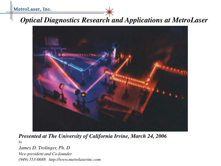
Optical Diagnostics Research and Applications at MetroLaser Presented at The University of California Irvine, March 24, 2006 by James D. Trolinger, Ph. D Vice-president and Co-founder (949) 553-0688 http://www.metrolaserinc.com. June 1988: Founded by Drs. Cecil Hess and Jim Trolinger.

E N D
Optical Diagnostics Research and Applications at MetroLaser Presented at The University of California Irvine, March 24, 2006 by James D. Trolinger, Ph. D Vice-president and Co-founder (949) 553-0688 http://www.metrolaserinc.com
June 1988: Founded by Drs. Cecil Hess and Jim Trolinger. 1994: U. S. SBA Distinguished Award of Excellence. 1995: U. S. SBA National Prime Contractor of the Year. 2000: Spun off 4DVision Technologies Inc. 2004: AIAA Aerodynamics Measurement Technology Award 2006: Ongoing collaborations with 14 universities 2006: 30 employees, 15 Ph. D’s. Thirteen electro-optical laboratories in Irvine CA. Providing State of the Art Optical diagnostic instruments, services, & research to government and industry. History and Achievements
MetroLaser has had joint contracts with UCI continuously for nearly 18 years. Over 30 different programs, subcontracts in excess of $2M. MetroLaser 4 fulltime employees and 10 interns from UCI. Currently have 3 active joint proposals MetroLaser/UCI Collaborations
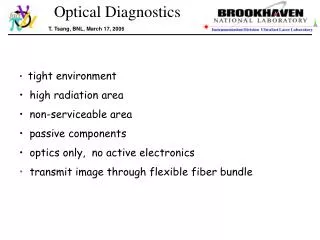
Laser Doppler Vibrometry Aerodynamic and Aero optic Measurement Technology Optical Sensors for NDT, monitoring, detection, and discrimination Tracking and Ranging for Space Situation Awareness Summary
Electronic Digital Holography (PhaseCam) Laser Doppler Vibrometry Single beam Multiple beam Matrix Applications Non Destructive Testing Modal analysis Machinery health monitoring Remote microphone Land mine detection Technologies for Vibration Analysis
Impact Testing of a Concrete Column in the Civil Engr. Lab at UC Irvine Typical Frequency Response of a Column Increasing damage Reduction of Natural Frequency With Increasing Damage
Automotive Experiments Use VibroMet 500 to measure the engine vibration as a function of engine speed
Automotive Experiments Variation of Peak Frequency and Velocity with Engine Speed
MetroLaser LDV Cart Array Lane 13, VS2.2., Depth = 1” Broadband Excitation, 80-300 Hz
Correlation of LDV Defect Data WithUltrasound Image of a F-15 Vertical Stabilizer
MultiBeam Full Field Application Dual Array Configuration Custom Matrix Configuration
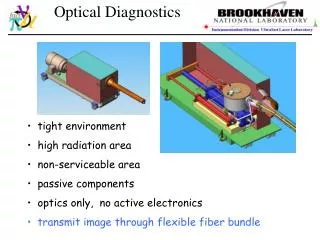
Holographic data stored on CCD array. Digital wavefront reconstruction Phase shifting interferometry (hologram plane). Diffraction theory (propagate to image). Interferograms are computed. Amenable to fiber optical implementation. Electronic (Digital) Holography
Commercial MetroLaser wavefront sensor Laser Object Beam Transmitting Lens Receiving Lens
Profilometry Detail of US penny shows 1 mm profiling resolution Discovering Lincoln in the Cent
Flow Visualization Holography Analyzing flow fields for density, velocity, temperature
Planar Doppler VelocimetrySystem for use in the AEDC 16 Foot Transonic Wind Tunnel Facility
AF03-251 (AC10) Fiber Optic Microsensors for High-Response Gas Total Temperature Measurement
Air Force Requirements High response measurement of total temperature distortion at up to 48 locations around turbine inlet. Minimum flow blockage from sensor array Robust against flow borne particulates Probe replacement with minimum down-time 8000 R/s T= 300 R
0 Task 2: Design of fiber optic microsensor Construction fiber cladding / 125m fiber core / 10m metallic mirror 0.01m FP etalon 1-2m ZnSe /Si/SiC metallic mirror 0.1m Characteristics Intrinsic solid state FP sensor Environmentally isolated high bandwidth response minimum flow disruption high density array deployment 125m 2m
scattered light metal surface detectors scanner scanner feature specular reflection Light Scattering Fatigue Detection
Notched Fatigue Sample 13 DP = 720 N N = 9796 N = 14096 Nf = 43736
Seed Visible & IR Radiation Active Laser Tracking System Concept CPU: System control & Data processing • 3D state vector • Velocity • Maneuvering • Vibration Laser Laser driver and controller Non-coherent Radiation Coherent Detection Coherent Radiation Propagation through atmosphere Target tracking, sensing & imaging Beam directing & telescope platform Control and Data Processing Platform
0.7O Laser Tracking System (Operational Principles) CPU NLM M2 Gain G2 P2 IR • Multifunctional detector-array • provides information on: • Delay time distance • Doppler shift velocity V • Spatial/angular coordinates Gain G1 M1 P1 Laser & Visible
Desired Imaging FPI specification • Tuning range: t > 5 nm • Bandpass width: p < 0.01 nm or p/ < 10-5 • Acceptance angle: p ~ 1 ~ 0.017 rad • Working aperture: 1.0 inch • Transmittance T040 – 50 % • Background rejection > 20 dB • Central-wavelength: ~700 nm
TDLAS System Layout for H2O z y flame x Fiber Beam launch InGaAs Detector ~3 cm 2-into-1 Fiber combiner w2 = 1392 nm w1 = 1343 nm Tunable Diode lasers Laser current controller Waveform generator Computer for signal processing
Results Comparison (T1) TDLAS temperature and CO2 chemiluminescence: EA = excess air: air beyond stoichiometric
Improving the Great Lakes Control of Air Pollution Monitoring and Remote Sensing Green Buildings Mining and Mine Waste Management Lead Paint Detection and Removal Agriculture and Rural Community Improvement Management of Animal Feeding Operations Drinking Water Treatment and Monitoring Pollution Indicators for Beaches and Recreational Waters Water and Wastewater Management Innovation in Manufacturing for Environmental Protection Nanotechnology Engine and Vehicle Emissions Reduction Solid and Hazardous Waste Homeland Security. Website- www.epa.gov/ncer/sbir/ EPA SBIR Opportunities-coming
Opened10 March – 10 April, 2006 Full Proposals 10 April, 2006 Deadline for AEROSOL COLLECTION INTO LOW ANALYSIS VOLUMES (ACLAV) RELIABLE PEROXIDE-BASED EXPLOSIVES DETECTION WITH LOW FALSE ALARM RATE ENHANCED EXPLOSIVE SAMPLE COLLECTION AND/OR PRECONCENTRATION SYSTEMS SIGNAL PROCESSING FOR A SOUTHERN BORDER SURVEILLANCE SYSTEM HUMAN DETECTOR FOR CARGO SHIPPING CONTAINERS INSTANTANEOUS REMOTE SENSING DATA RECEIVING AND PROCESSING FOR EMERGENCY RESPONSE NETWORK-BASED BOUNDARY CONTROLLERS BOTNET DETECTION AND MITIGATION MANAGING MULTI-MEDIA SURVEILLANCE INFORMATION NETWORKS Homeland Security SBIR
You can download this presentation from our website: www.metrolaserinc.com Thank you for your attention